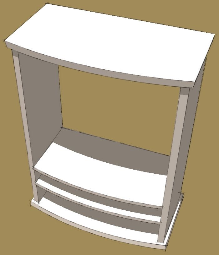
When you are working in the shop on a project, there comes a point where you need to shift from working off the plans to working off what you’ve already built. Doing so helps to avoid making parts that don’t fit. In SketchUp, the same thing goes. Tim Killen and I have written about drawing parts in place. It is easier to work that way and it’s also more accurate. Here’s a demonstration of this.

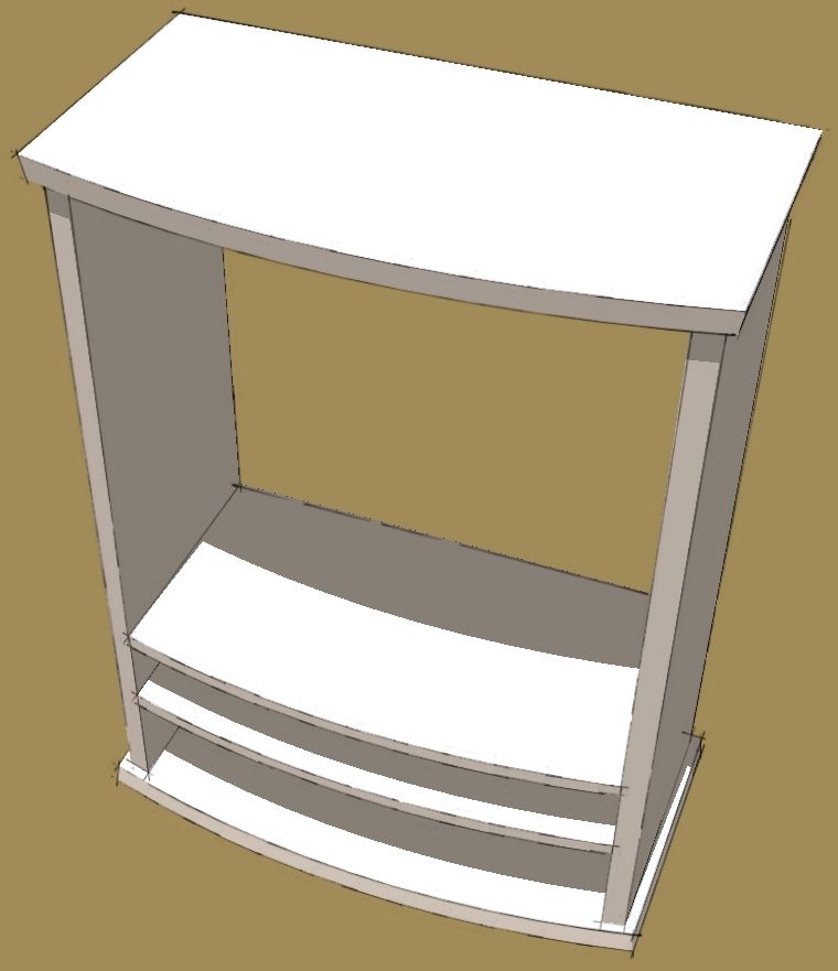
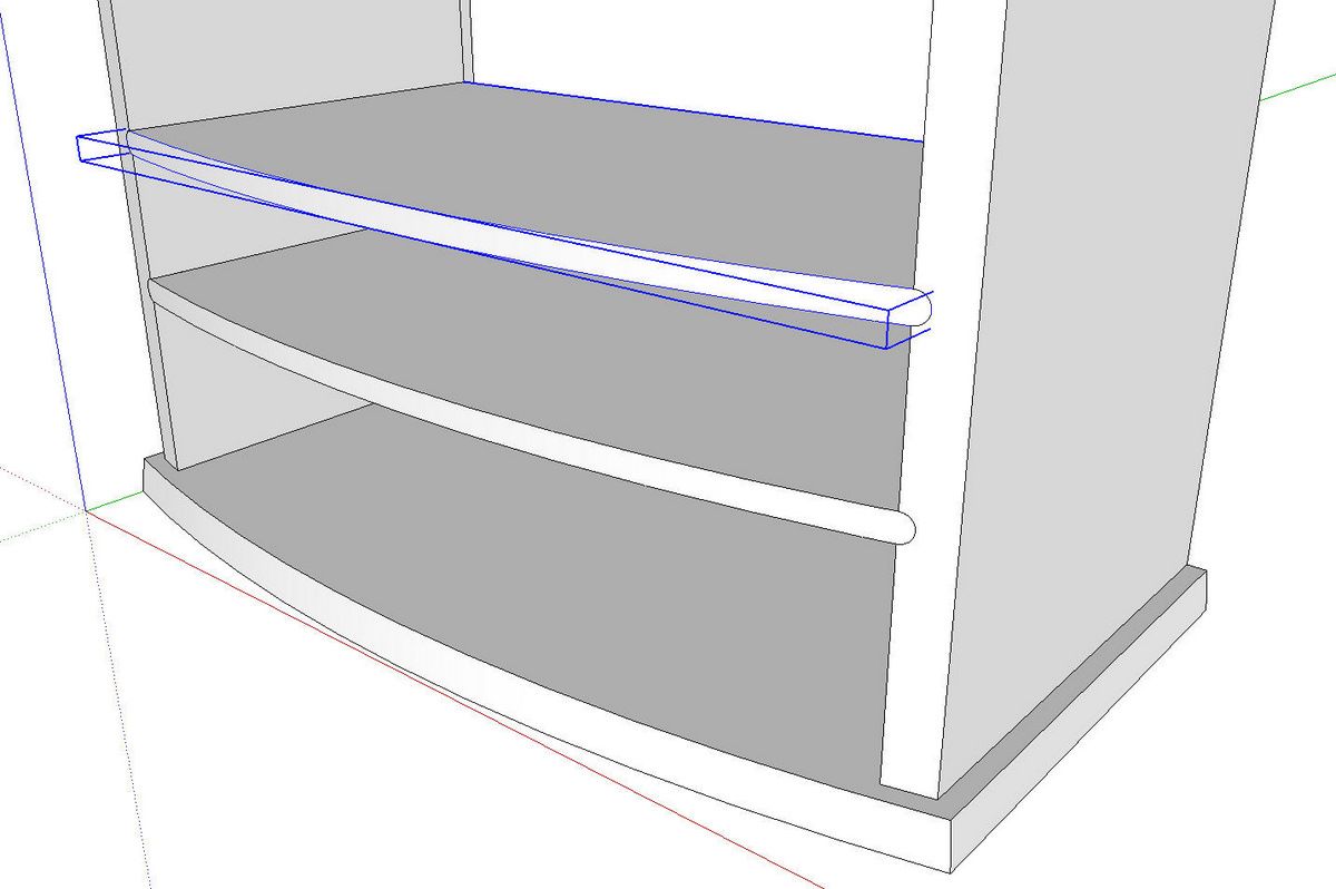
Fine Woodworking associate editor, Matt Kenney has been working on a design for a bow front cabinet. He asked me if there is an easy way to draw the dividers so they fit and have the right curve on the front edge. This is the way I showed him to do it.

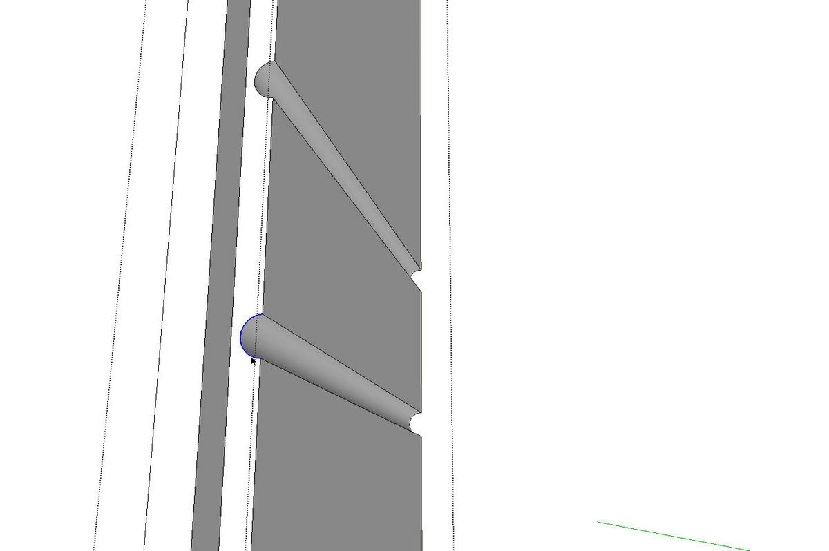
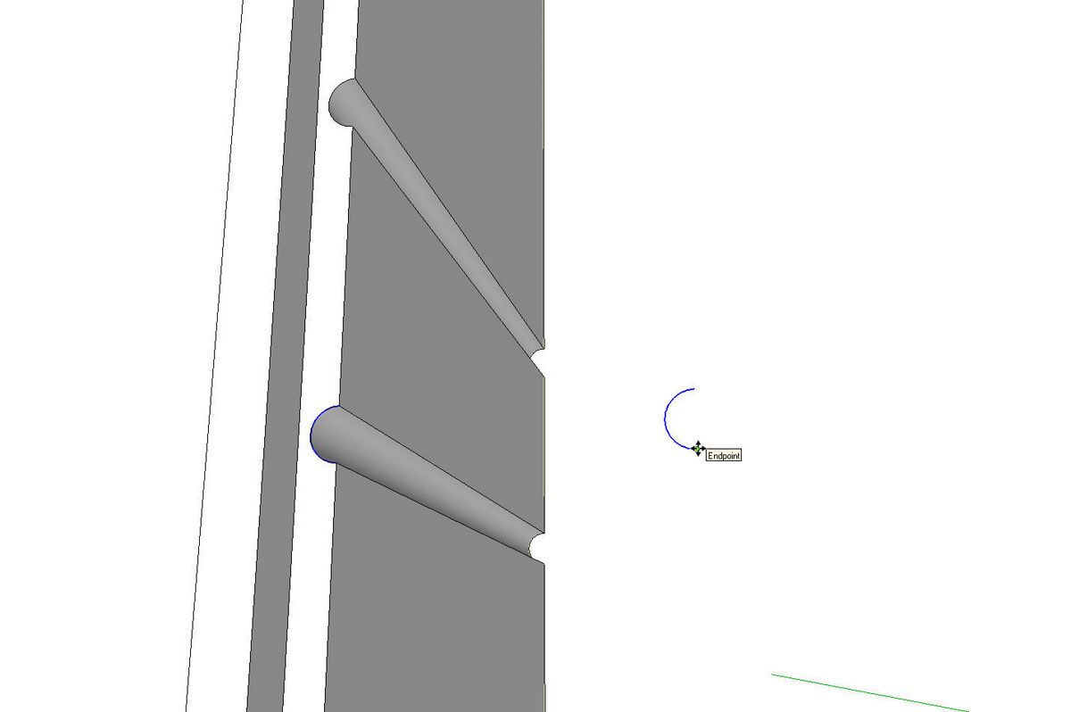
First, I orbited around to the back and opened one of the side components for editing. I selected the arc at the end of the cove and copied it using Ctrl+C. (Edit>Copy or the Copy tool work as well.) Then I closed the component and used Paste in Place from the Edit menu.

Next I copied the arc with Ctrl+Move then mirrored and placed the copy in the cove on the opposite side. You could also just open the other side component and repeat the Copy and Paste in Place procedure.

Then I used the line tool to connect the arcs to form the back edge of the divider.

Then I used Push/Pull to make the divider 3D. The distance isn’t critical as long as it extends beyond the front of the case.

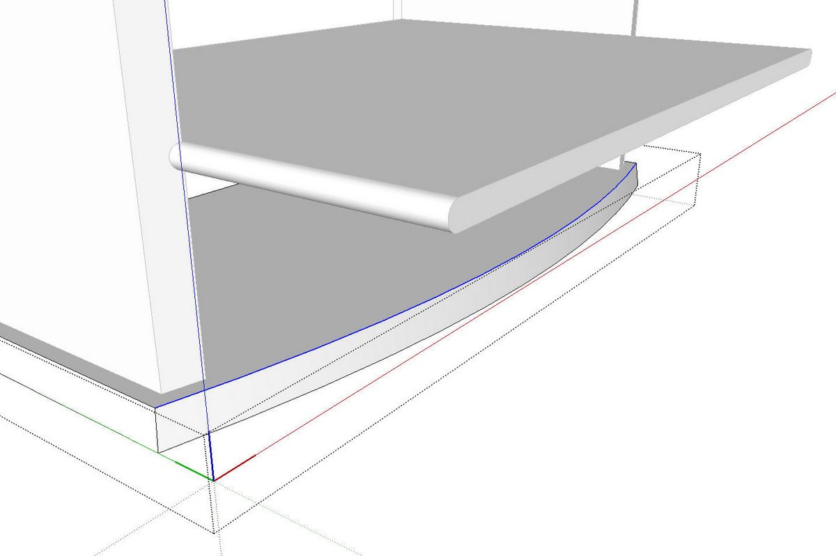
Now, to cut the curve on the front I started by opening the bottom component and copying (Ctrl+C) the arc on the edge. I closed the bottom component and used Paste in Place to paste the curve.

I used the Tape Measure tool to measure the distance between the front edge of the side component and the curve. To be strictly accurate the measurement for the offset distance should be measured radially from the arc to the upright. this can be done by setting a guideline perpendicular to the segment of the arc nearest the side component using the yellow Protractor tool. Place the guideline so it intersects the front edge of the side.
The difference between measuring radially and just measuring orthogonally in this case is less than 1/128″ and it would probably be nit picking to worry about it. In cases where the offset distance is larger, it might be worth the extra time to set up that way.
Then I used Offset to create a new curve at that distance.

I connected the two curves with line segments to complete a face.

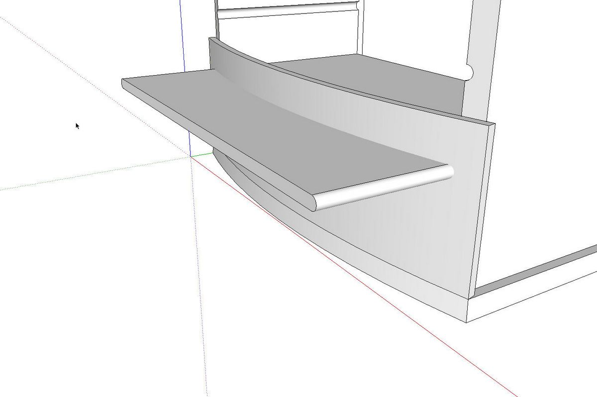
Then I used Push/Pull to pull that face up through the divider. Notice there’s no edge where the vertical surfaces passes through the divider.

I selected all of the geometry for both the vertical extrusion and the divider. Then I ran Intersect>Intersect Selected.

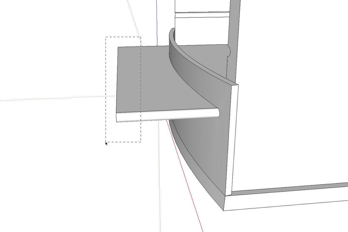
After the intersection is completed, it’s time to delete the waste. A right to left selection box on the front selects the part of the divider that extends forward of the curved extrusion. The Delete key makes it go away.

And here’s a close up of the end of the divider.

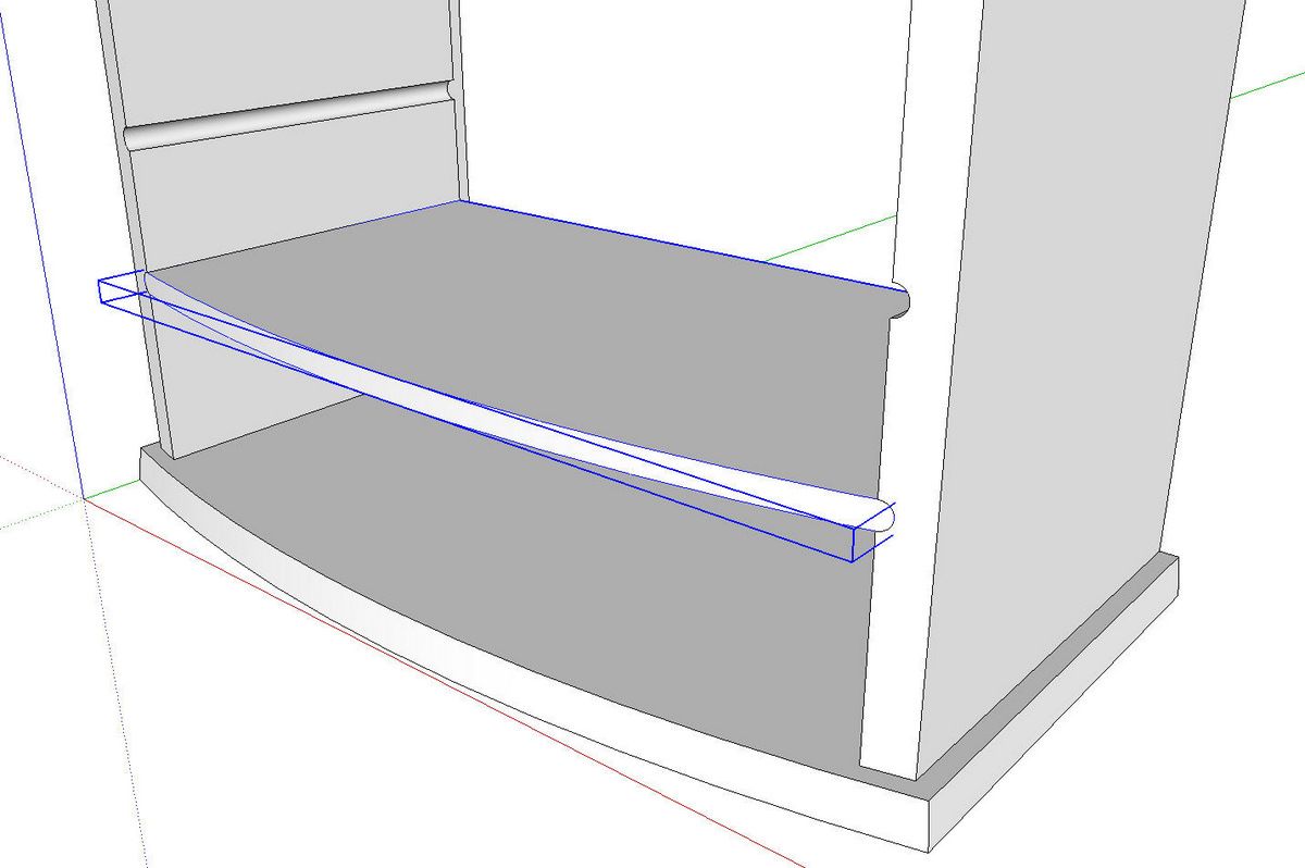
After the rest of the waste is deleted, correct the face orientation on the front edge of the divider and make a component.

Finally, copy the component with Ctrl+Move to make the other divider and that completes them. It’s a perfect fit and there was only one dimension I needed to know.
Matt’s plan is to make drawers for this cabinet. The drawer fronts will have a complimentary curve and can be drawn using the same basic method I used for the vertical extrusion and there’ll be no question about them fitting. As to how he’ll make them in wood…well, that’ll be up to him.




















Comments
"I used the Tape Measure tool to measure the distance between the front edge of the side component and the curve."
Given the combination of geometries it might be useful to give more detail as to how you measured this distance. The distance measured orthogonally, referenced from the side, will be larger than the distance measured radially from the arc. Given how small the actual dimensions are in this particular case the difference would be very small but still real. One needs to pay special attention when working with a combination of orthogonal and radial geometries.
If the offset distance was greater, your point would be valid. As it is in this model, the difference between the orthogonal distance and the radial distance is less that 1/128" and inconsequential. In any case I did use the radial distance.
Please ignore my previous post since it has been deemed invalid (even through it is in fact accurate).
Log in or create an account to post a comment.
Sign up Log in