Build a Contemporary Sideboard
Chris Gochnour's sideboard combines usefulness, strength, and beauty in a contemporary case piece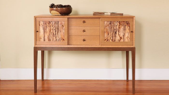
Synopsis: The half-blind mitered dovetails used to join this sideboard help make it strong and beautiful, with grain that runs up one side, across the top, and down the other for a waterfall effect. All the other joinery is hidden and employs Domino slip tenons. The sliding doors are punctuated with spalted live oak veneers. Follow along as Chris Gochnour shows how to build this classic yet modern beauty, step by step.
Sideboards are among my favorite pieces of furniture to build. They offer great utility—whether used in a dining room for dishware or a family room for entertainment equipment—and they invite a wide array of approaches in terms of structure and joinery, materials and finishes. With care taken in the design phase, the sideboard form is also often quite beautiful.
For this sideboard I used half-blind mitered dovetails to join the case, providing excellent strength but also enabling me to create a waterfall effect at the ends of the top—the grain runs continuously up one side, across the top, and down the other side . For the other joinery in the piece, none of which is exposed, I used Domino slip tenons. I built the case with solid riftsawn white oak, which has quiet grain and a tawny tone. That set the stage for some splashes of color and figure in the panels of the sliding doors, which were made with veneers of live oak that I sliced from a spalted firewood log. I built the base with white oak, but to differentiate it from the case I darkened it by fuming with ammonia.
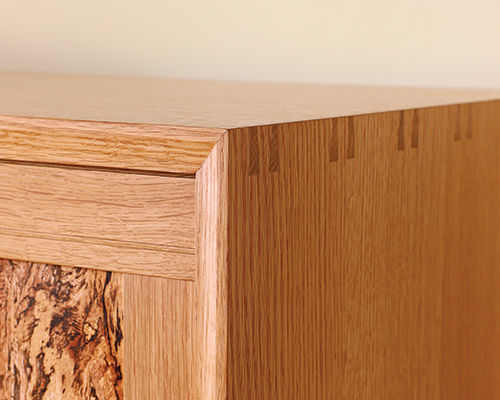
Half-blind mitered dovetails: traditional layout with a twist
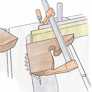
I love the strength and integrity of the half-blind mitered dovetail joint and the classic aesthetic impact it adds to a piece. For this sideboard it also offered minimal interruption of the waterfall grain pattern I wanted. You can cut the joint largely with machines (see Master Class, FWW #236), but I find it simpler and quite efficient to cut it mostly by hand.
As with typical dovetail joinery, I cut the tail portion of the joint first. on this sideboard, the tails are on the cabinet sides, so that’s where layout starts. The layout differs from conventional dovetails because here you’ll want the joint to end with a half tail at the front and back of the case instead of a half pin. This is essential due to the miter that will be cut later. one other thing that sets the layout apart is that the full baseline is scribed only on the interior face of the tail and pin boards. on the tail boards there is a baseline on the outside, but drawn with a pencil. After the tails are laid out, I use the marking gauge to scribe a partial baseline on the outside— but scribing only in areas where wood will be removed. Although I milled the stock a smidge thicker than 3/4 in., I set the marking gauge for scribing the baseline right at 3/4 in. This leaves a tiny flat at the tips of the miters when they are complete. The flat is removed after glue-up, bringing the miters to a seamless corner.
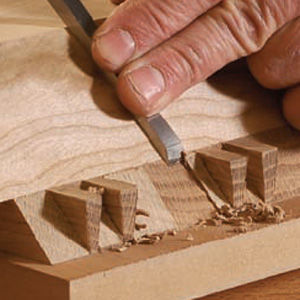 |
Article: Dovetailed, mitered and half-blindThere is a lot going on in the case joinery of Chris Gochnour’s sideboard. In an online feature, Chris shows you how to tackle this devilish dovetail step by step. |
**Corrections
Several dimensions in the illustration on pp. 34 and 35 of FWW #277 (“Strong, Stunning Sideboard”) were wrong.
- The door stile is 11-1⁄2 in. long (including 1-in. tenons), not 9-1⁄2 in. as printed.
- The drawer back is 14-7⁄8 in. long, not 12-15⁄16 in. as printed.
- The partition groove is inset 3⁄16 in., not 5⁄8 in. as printed. The inset for the top, bottom, and sides is 5⁄8 in.
From Fine Woodworking #277
To view the entire article, please click the View PDF button below.
Fine Woodworking Recommended Products

Blum Drawer Front Adjuster Marking Template




Comments
Beautiful and simple, and a well written article. Not a criticism but a concern: My first thought was that the base rails are too long to support the weight of the cabinet without stretchers, but the description and use of the "Barnsley" joint is something that I want to look closely at. I like the clean, minimal look of the base, but I would always worry about the inevitability of someone dragging a fully loaded sideboard across the floor, and leveraging the legs. I probably worry too much about things like this, and I really do like it better without stretchers.
I'm trying to use the half-blind mitred dovetail joint on a slightly larger cabinet that I'm making from white oak. I've done several test joints. I'm struggling with the "little flap" that is to be left on the ends of the mitres. When I do that, by setting the marking gauge just shy of the width of the stock (as suggested) the pins do not push fully through the tails. Perhaps my pin mitres are off. Any advice would be welcome.
I'm not an expert on this but reading through the text in the article and thinking about the joint, it would seem to me that the pins shouldn't quite meet the outer face of the tail board when you first put it together. Mr. Gochnour planes the outer faces down to get rid of the tiny flat at the end of the miters and in the process should bring the surface down to the pins.
I made a quick illustration.
The pin board would look something like the first image. After assembly, like the second, and after planing, like the third.
Dave - Wow, I’m overwhelmed by your kind and thoughtful reply. Not only does your explanation make a lot of sense, you even drafted three Sketchup diagrams! It may turn out that this joint is beyond my skill level, bit you’ve inspired me to continue my test efforts to try to get it right. Thanks a million!
I'm happy if it helps. To be honest, I had already modeled the case for a Design. Click. Build. blog so it was an easy thing to pull it out, add a little thickness to the case parts and make the screen grabs. That old adage about pictures and words is true.
I expect if you've been able to cut the test joint and get it to go together, you have the skills to do it. Don't give up.
Dave
I REALLY would love to see a video workshop on this piece. It’s just stunning
Were the pulls turned on a lathe or ordered pre-made? If pre-made, where can I find the same ones? Thanks so much. Looking forward to building this beautiful piece.
Considering that the dimensions and profile of the pull is shown in the article, I expect Mr. Gochnour made his pulls and the lathe would make the most sense. I suppose for your version of it, you could use store bought pulls if you want.
Does anyone see the inset distance from the front for the top and bottom groove for the sliding doors? Is it in the diagram but I am missing it? This is an important measurement so the doors slide across the inset drawers.
I don't see anything to indicate that dimension but some figure shows it must be between 5/8 and 7/8 in from the front edge of the top and bottom (Not measuring from the cove but the actual edge of the board). From the photos in the article it appears the drawer fronts sit slightly behind the front edges of the vertical partitions. With the drawer fronts 1/8 in. back from the front of the partitions and the front of the groove 7/8 in. back, I get about 3/64 in. of clearance. A little snug for me. At 3/4 in. back, the front of the door rails would be about 1/8 in behind the cove.
FWIW, you could do what I've done to figure this out and create a model in SketchUp or some other 3D modeling application. This would make it easier to work out details like this and let you visualize them before cutting wood.
Thank you, Dave. I didn’t think I had missed it somewhere. Yes, a 3-D model or something like that with all the correct measurements would be very helpful. This is a somewhat complex piece with lots of important details and some of us have invested a lot of time and some fancy figured wood building it. Thanks again.
Where can I find the 1 3/4" radius cove bit mentioned in the article. It was used to inset the drawer pulls. Can't seem to find one that size online.
I think there's a typo in that description somewhere. Probably the bit should be listed as 1-3/4 in. dia., not radius. If you used a 3-1/2 in. dia. cove bit and plunged it in 3/8 in., the perimeter of the recess would be more than 2 in. in diameter.
FWIW, a quick search for cove router bits turns up large bits for making crown molding like Infinity Tools 56-602 which is 1-3/4 in. dia.
I'm a bit confused over the Domino Tenon lengths listed at 40 mm, as a 20 mm Domino Mortise would exceed the 3/4 inch (.75 inch) thickness of the case top and bottom (2mm = .79 inch). Is the tenon offset deeper into the partition?
I don't see anything in the article that calls out the depths of the mortises but I would expect to make the mortise deeper in the vertical pieces and not go more than 12 or 14 mm deep in the top and bottom panels.
How did he end up finishing the piece? Same over both the fumed and unfumed portions? I'd love to try fuming to get that rich chocolate brown but uncertain where to go after the fuming.
I'm looked at various parts of this article over and over...its a good one! Maybe less complicated than working out all the offset and reveals, but still a missed detail is how and when he set the 5mm shelf pin holes. One set is on each case side and each opposing/mating set are in the recessed partitions. Did make two separate jigs - one for side and another for partition? Drilled before glue-up and risk them not being perfectly registered? Or drill after glue-up and register the jigs to the case bottom?
Log in or create an account to post a comment.
Sign up Log in