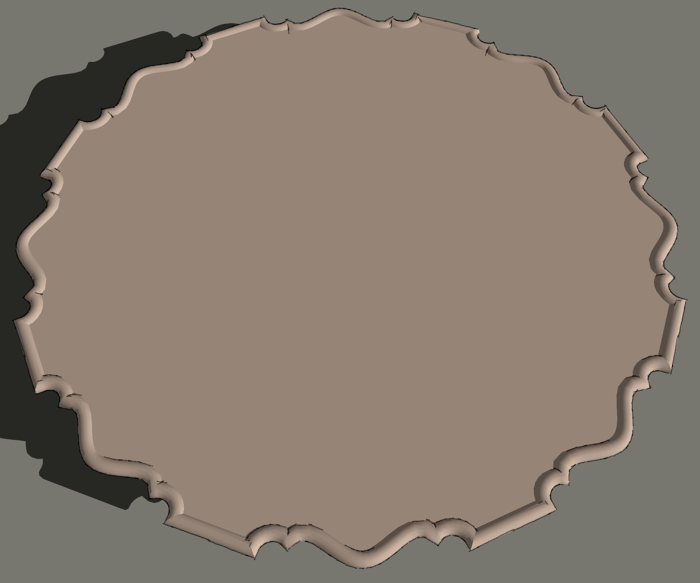
I got an e-mail today from a good friend of mine. He is working on a pie crust table in SketchUp and wants to show a couple of edge treatment options. He also discovered after drawing the table top that the file size is quite large and he asked for a way to reduce it. Here’s my approach to handling these things.
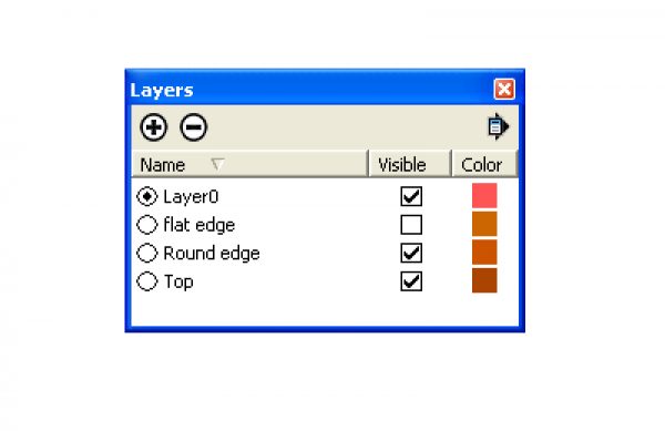
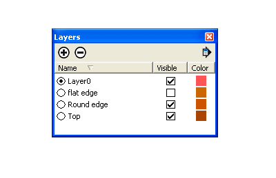
To get started I created three layers using the Layers dialog box found under the Window menu. I clicked on the ‘+’ sign in the circle to create new layers. I named them for each of the parts I wanted to separate out in the model.
Here are a few important points to keep in mind about layers in SketchUp:
- Layers only control visibility. They do not provide separation between elements in the model.
- Layer 0 is the default layer and cannot be deleted.
- Layer order doesn’t have any effect on the model. In applications such as PhotoShop, layer order does have an effect on appearance but not in SketchUp.
- The radio button to the left of the layer name indicates the active layer.
- Always leave Layer 0 as the active layer.
- Draw all entities on Layer 0. Assign different layers to components or groups but leave the edges and faces inisde components/groups on Layer 0.
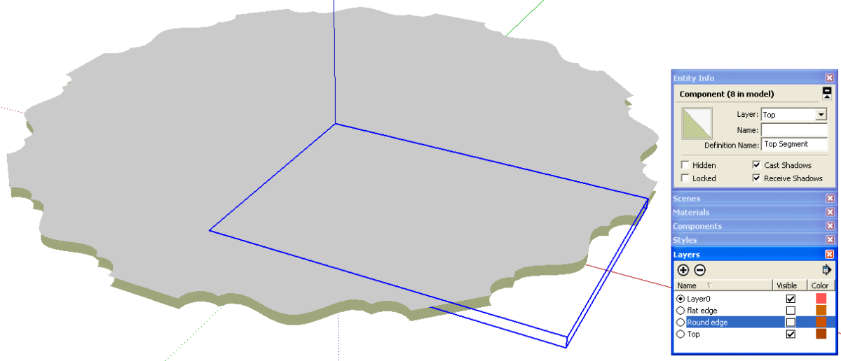
The image above shows the layers for the three parts of the top with the visibility of the flat edge turned off. Layer associations are changed in Entity Info.
The pie crust pattern I worked from breaks down so that the shape repeats every 45° around the top. I drew only that part of the top and made it a component which I assigned to the layer called ‘Top’. Then I used the copy function of the Rotate tool to make a radial array of that component to complete the top surface. That is, I selected the component, got the Rotate tool and hit Ctrl (Option on Mac) to invoke the copy function. I copy/rotated the component about the center point. I typed 45, hit Enter, then typed *7, Enter. Note that 7*, x7 and 7x would also work for making the copies.
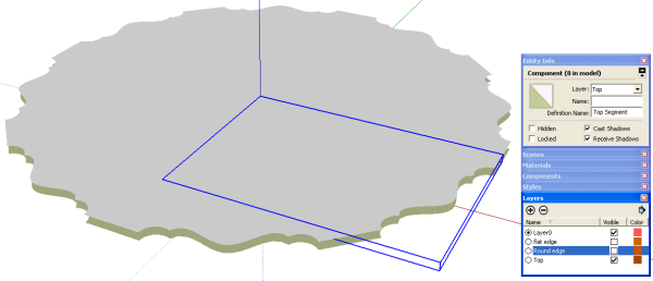
After copying the component, I delete all of the vertical faces and edges. I also hid the seam lines and extrerior edges because we don’t want to see them. It is important to delete the vertical faces or the seams will show even if the edges are hidden.
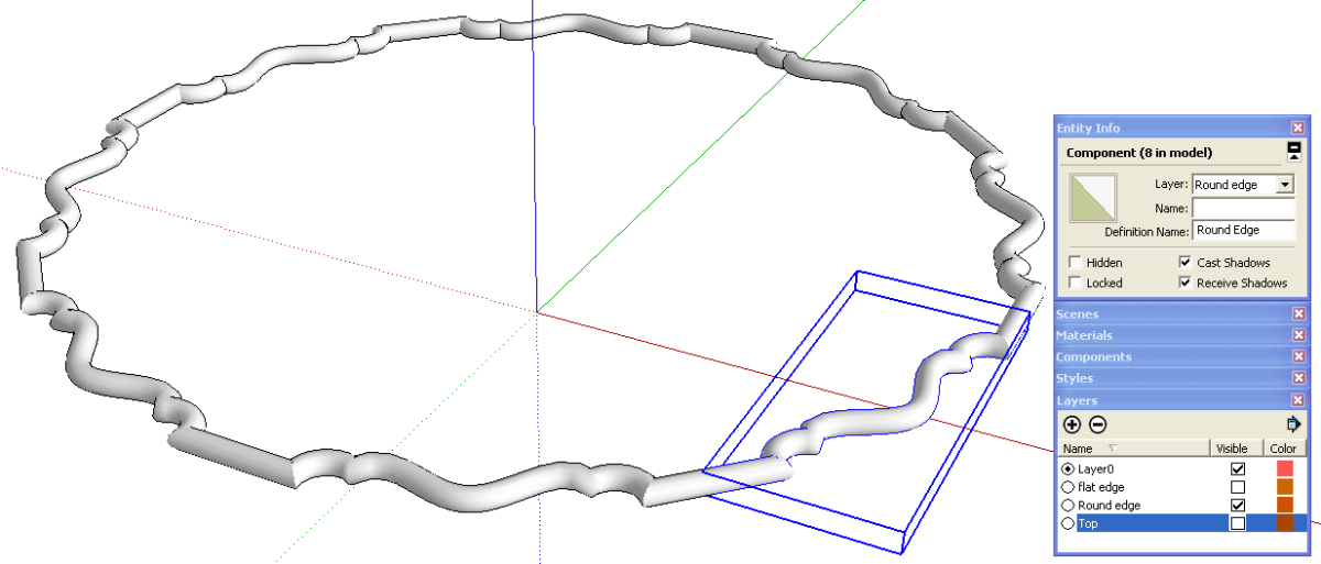
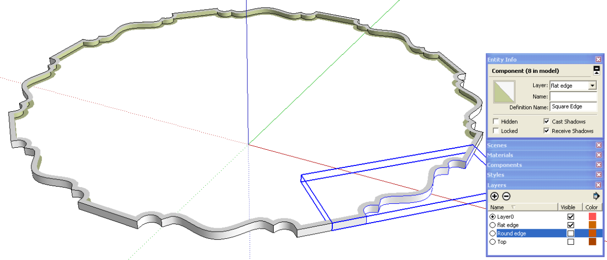
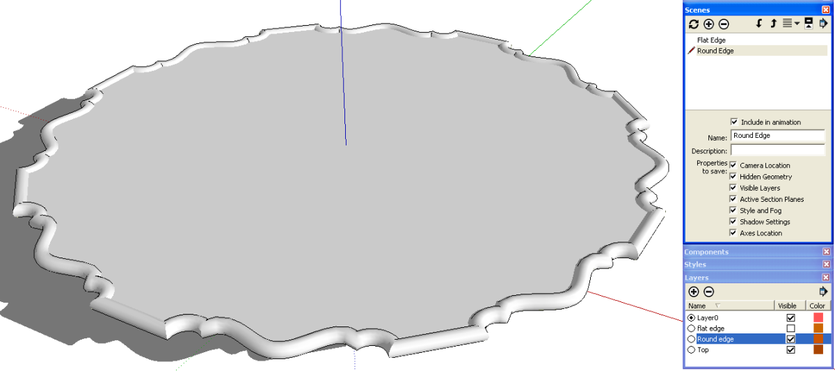
I used the same edge from the top fas a path for Follow Me for both a round profile as well as a square one as you can see in the next two images. I made each of those extrusions into components and gave them the appropriate layer associations. Then I copied them around the center as I did with the segments of the top.
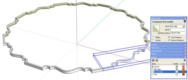
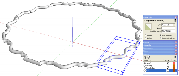
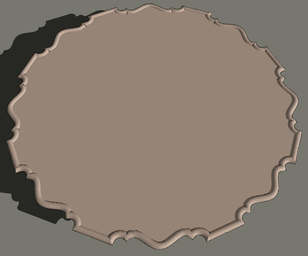
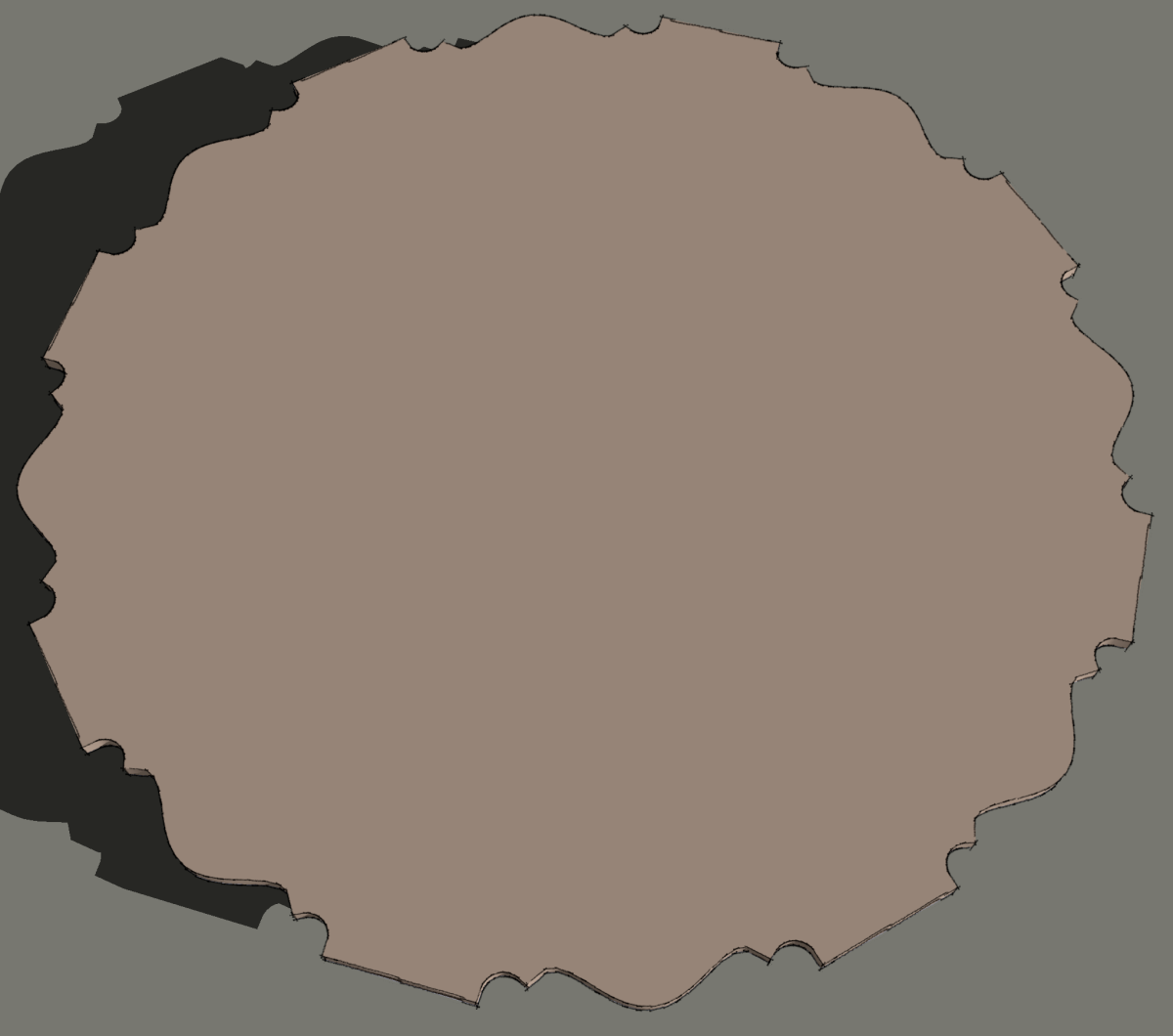
So, now with the parts drawn and copied and with the layer associations made, we can easily switch between the flat edge and the round one to see the variations in the top. It’s just a matter of changing which visibility boxes are ticked in the Layers dialog. But we can make it easier yet to switch between top styles.
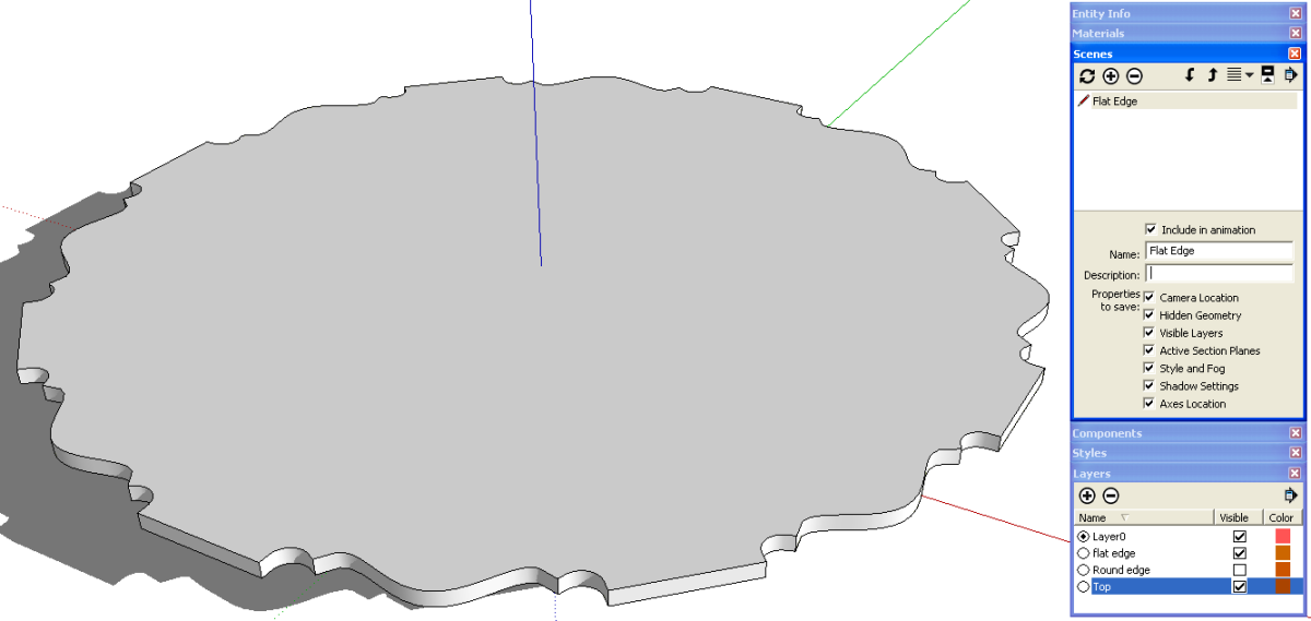
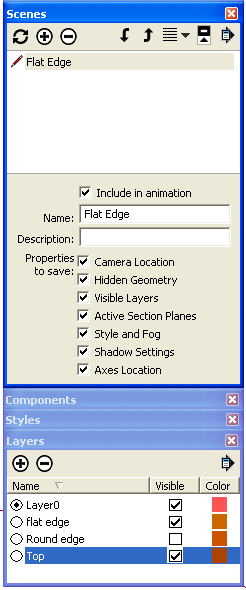
We’ll open the Scenes dialog under Window and create a couple of scenes. Think of these as snapshots of the model.
For the first scene we’ll have the top and the flat edges visible. Then we click on the ‘+’ sign in the circle to create a scene.
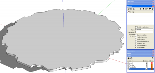
When you make the first scene it will be named ‘Scene 1’. You can replace its name by typing a new one in the Name box.
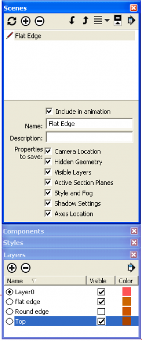
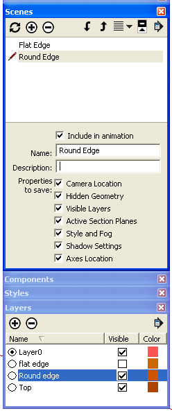
Next well turn off the flat edge and turn on the round one and then create a new scene.
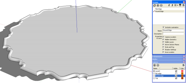
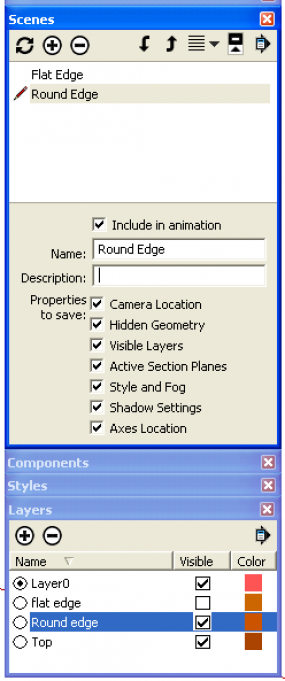
When the scenes are created, the camera position is normally saved as well as the style and the other properties shown under “Properties to save.” You make changes to any of these properties for any given scene and click on the circular arrows in the Scenes dialog to update the scene or you can right click on the scene tab and choose Update.
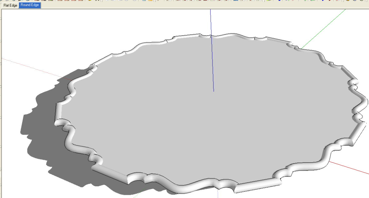
When you’ve created your scenes, you see tabs at the top of the drawing window. On the PC they fill in from the left. On the Mac they are centered over the drawing window.
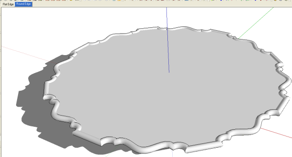
You can make image exports of your scenes a couple of ways. You can select each scene in turn and go to File>Export>2D and make the images or you can use the animation export option. If you diabled Scene Transitions under View>Animations>Settings, you’ll only get images for each scene. Change the file type to JPG or PNG as desired and under Options set the desired export size.
I wrote about showing variations in a model using the same method in Trying on a Different Look and the same ideas can be used to make it easier to show otherwise difficult details by putting various components on layers and controlling their visibility. Also, regarding the use of layers, you might find this old post of some use.
And in case you’re interested in the file size, my friend’s version was 4.3 Mb with just one version of the edge while mine with both versions saved out at 268 Kb. His edge profile is slightly more complex than mine I divided his model into sixteenths and did some clean up and got it down to 212 Kb.



Comments
Thanks for the information about image exports. I wanted to ask you about saving components for future use. You wrote about it on december of 2009, on the google sketchup 7. Could you update that information for sketchup 8. Thanks on advance for your help.
Hi Ocampo. I could write something up on saving components although the process is still exactly the same for SU 8 as it was for version 7.
-Dave
Log in or create an account to post a comment.
Sign up Log in