Connect Legs with rail Sketchup help
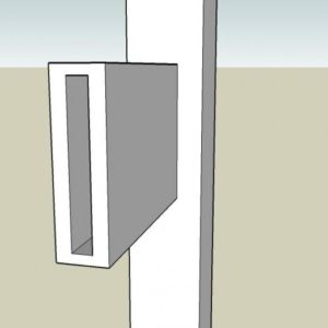
I have been learning Sketchup and the tutorials have been a huge help. I was looking at Dave’s video on the circular table. In that video he connects two legs with a rail and he draws the mortise, then drags a rectangle and extends it along the plane to the other leg as a solid piece. He then goes to x-ray to go in and extend the tenon into the mortise. For some reason when I do it, I get the mortice recessed in the leg, but when I draw the rectangle and attempt to extend the to the oposite leg, it takes the opened mortise with it (see jpeg). What am I doing wrong?
Thanks
If it moves, tax it. If it keeps moving, regulate it.
And if it stops moving, subsidize it.


Replies
Hi bones,
Have you been making components of the parts as you go? My guess is no and if that's right, that would cause your problem. By making the leg and rail into components, they remain separate pieces just like the pieces of wood you would use for those parts.
Draw the leg, make it a component and then draw the rail and make it a component. Edit each component to add the mortise and tenon as appropriate.
Does that help? If you need more assistance, I'll be glad to give it although I'll be tied up this morning with an anesthesia student.
Dave
Thanks for the reply Dave. I've done it from scratch and just making a leg and making it a component. I create the mortise, extend a rectangle around the mortise, and when I use the pull tool, it brings the mortise opening with it? I went back and tried it without making the leg a component and I could extend it as a solid piece, but could not get inside the leg to select the section of the rail as a face to pull ento the mortice opening to make the tenon. Government's view of the economy could be summed up in a few short phrases: If it moves, tax it. If it keeps moving, regulate it. And if it stops moving, subsidize it.
If you are editing the rail component nothing you do to it will affect the leg component. If you can't see inside the leg to work on the rail component you can try a couple of things. Under Winodw>Model Info>Components, adjust the slider for Fade rest of model. The direction you slide it may be dictated by the way your video card is handling OpenGL so you can experiment. Also look at Transparency under Styles>Edit>Face Settings (the tan cube icon) and make sure the check box is checked. Also try the different settings for Transparency Quality. finally, try setting the front and back face colors so there is more contrast as this might help with the display.
An alternative to editing in place is to make a copy of the component and move it away from the rest of the model. Edit it as needed. Since it is a copy of acomponent, all other instances of the component get edited at the same time. When you've completed the editing delete the extra copy of the component. If you know the details for the tenon--shoulder width and tenon length, you might find this method easier than exercising your Superman X-ray vision.
Helpful?
Dave
Thanks for the help! I went back and looked again being careful of the states of the two componenets. I finally discovered that I was not selecting edit component. Once I added that step, the problem was resolved. I can now make the mortice add a rectangle and extend it to the second leg and use x-ray to go in and pull the tenon into the mortice.
I tried an alternative method when I earlier could not get this one to work. I created the tenon on the end of the rail and extended the tenon into the leg and used intersect with model to create the mortice opening and then pushed the mortise to the proper depth in the leg. Whew, this has been a long learning curve, but I'm getting there. It took me hours just to get the reference line thing down pat!
Thanks again for all the help, love the videos!Government's view of the economy could be summed up in a few short phrases: If it moves, tax it. If it keeps moving, regulate it. And if it stops moving, subsidize it.
I'm glad you got it worked out. Keep plugging away and it'll all seem easy.
FWIW, I just made a new blog post. Here's a link. http://blogs.taunton.com/n/blogs/blog.aspx?nav=main&webtag=fw-designforum&entry=55
Thanks for the link. I've watched your other stuff and it has been a godsend. In this case I found that if I create the rails and tenons prior to making them a component, it seems to be easier. Here is a day's work! Does not seem like much, but I know a lot more now. I did the right side painstakenly, made a group out of the legs & rails, and then rotated 180 degrees and renamed each component for the left side. I discovered a problem though that you might have a simple solution for. When I rotated the right side around to make the left side, I found out that I was out of square to the right side by 2.2 degrees. It did not show up till I zoomed in to create a mortise for the top rear rail and noticed it did not look right. It took me a while to figure out how to fix it. I used the protractor to measure the degree out of square, and then used the rotate tool to move the left side back into square. Is there a function that will more easily do this, i.e. lock onto a axes. In this case the green axes. Don't get me wrong, it was a good learning experience, but what a pain. Government's view of the economy could be summed up in a few short phrases: If it moves, tax it. If it keeps moving, regulate it. And if it stops moving, subsidize it.
2.2°? In my shop I call it square if it's 90°+/- 10%! I'm just kidding. ;)
Rotating: Keep the cursor near the rim of the protractor and it will snap to the nearest 15° mark. Or, after starting the rotation, type 90 and hit Enter. During rotation or when setting angled guides/measuring angles, the Value Control Box accepts angle values (or pitch if entered as a ratio, x:y)
Rotating the leg assembly creates some problems when things aren't the same front to back. It puts the back leg on the right in the front position of the left. Instead, make the copy and move it into place on the left side. Then mirror the assembly with the Scale tool as I did in that last video. If you look at the one on the dovetailed box, I did it several times there as well. Select the component or a collection of components, get the Scale tool. Hold Ctrl to "Scale about center" and push one side through to toward the opposite side. Type -1 and hit Enter. In the case of your leg assmbly, push the right side through toward the left side when mirroring.
An easy way to think about this is to consider the component, say a leg, as the piece of wood in the shop. When it and its counterpart are complete--all joinery is done--would they be interchangeable? If the answer is no, rotating the component in the model is the incorrect approach. Mirroring would be the solution since they would be mirror images of each other.
Also, instead of making a group of the rails and legs, make that a component also. It would be considered a nested component. That way, if you need to make a change to, for example, the height of the bottom rail, you only have to move it on one side while editing the nested component. The opposite side will get the same work done to it.
A couple more things I think you should consider doing.
Change your starting template.
*Delete the component and purge it from the In model components. *Under Styles>Edit>Edges uncheck Profiles. (they can be nice to look at but they are a pain to draw with.) *Under Window>Model info>Units set to Fractional, Precision: 1/64" and uncheck Enable Length Snapping.
Do this with a brand new, blank drawing. then File>Save as... (not Save) and save the file in Program Files/Google/Google SketchUp 6/Templates. Give it a name you can remember. Next go to Window>Preferences>Templates. Click on Browse and select the file you just saved. Hit OK. Next time SketchUp will start with those settings in effect.
Personally I prefer the sky turned off and the background color set to white. You can do that if you want under Styles>Edit>Background. Do this before the Save as and it'll also be part of the starting template.
Dave
Thanks for all the help. I loved the scale -1, so much easier. Can you delete a component definition without deleting the part in the drawing? Is that what explode will do?Government's view of the economy could be summed up in a few short phrases: If it moves, tax it. If it keeps moving, regulate it. And if it stops moving, subsidize it.
Explode will make the collection of geometry not a component (or group) but it won't remove it from the In Model component list.
Why do you want to delete a component definition?
Sometimes I was playing and found I had created too many names and just wanted to clean things up, but when I went into window and browse the components different flavors of the same componet existed. I had hoped I could delete the component name (start over) and leave the drawn image intact or drawn without a component defined. When I deleted the name, any drawn parts went with it.
While I'm here, I have another challenge. I'm trying to make a board with an arch in it. The push pull will not work, but I found that if I draw the board and put an arch on the front, and back and then use the erase tool, I can get what I want, but the surface that is the curved surface goes away, and is now open, like a hoolow board. I want to close the curved surface, but cannot find a way to do it. Here is a pic. Thansk in advance.
Government's view of the economy could be summed up in a few short phrases: If it moves, tax it. If it keeps moving, regulate it. And if it stops moving, subsidize it.
Keith,
I'm going to have to delay the response I want to write until this evening. Could you draw that again and e-mail the SKP file to me. Save the file immmediately before you would push/pull.
drkr4109 at gmail dot com.
Edited 11/1/2007 2:47 pm ET by DaveRichards
Here is the file. Thanks. If I do the arch on the flat rectangle then do a push pull it works, but in this case that would not work. the pice is there already, so I need to do the arc on the board and cut away the waste. Hard to explain.
Government's view of the economy could be summed up in a few short phrases: If it moves, tax it. If it keeps moving, regulate it. And if it stops moving, subsidize it.
Keith,
I'm sorry but I don't know why you had a problem. I copied the top face of your piece, Used Push/Pull to make it the same height as yours and then drew an arc from corner to corner. Push/Pull create the cut out without deleting the face on the inside of the curve.
Could you go into more detail about how you drew this? Did you already have the component made? Did you draw the arc while editing the component?
Dave
Edited 11/1/2007 5:35 pm ET by DaveRichards
Keith and Dave-Just for the record: It's a long way around, but the original open-bottomed component can be salvaged by drawing lines connecting the endpoints of the line segments composing the two arches. Softening these lines (Erase + Option) will complete the component.
Thank you Donald. I did know that and would have suggested it if I thought there wasn't any other way around the problem. It shouldn't have occurred in the first place so we're trying to cipher out what happened to cause it. There must be some reason why SketchUp is not creating the face (really faces) during the Push/Pull action. I need to find out more from Keith about how he's constructed the rail to begin with. I think the problem lies with that and the arch on the face.
Cheers,
Dave
BTW, that arch is simple enough but I doubt anyone would want to have to salvage the faces curves of something like Lonnie Bird's Pipe Box.
Some confusion sorry about that. What I did was use your method that you demonstrated in the round table video. I formed the mortise, and then added the flat square over the mortise and pulled that face to the other leg. That created a standard board so to speak 2 1/" 3/4" by the width of the two legs. I then set two reference lines 1" in from each side of the leg running up and down. I then put a reference line in the middle and pulled an arc up 1" from the top out to those reference lines. I did this on both sides and used the erase tool to cut the waste away at the bottom to cut away waste. This left the open face that I sent you. Anyway, I see that the easier way would have been to make the flat face with the curve and pull it to the proper thickness then move that piece into place. I just liked the extending the rail from one leg to the other. Government's view of the economy could be summed up in a few short phrases: If it moves, tax it. If it keeps moving, regulate it. And if it stops moving, subsidize it.
Keith, you can certainly pull the rail out as you did. Just draw the arc on one side and use Push/Pull to push the arc through to the other side. Remember that you aren't using a solid modeling program. SketchUp only does faces. So if you delete as you were doing, you will end up with the missing faces.
Read only is a bunch of crap.. I thought we were friends in here!
I'm not sure what you mean?Government's view of the economy could be summed up in a few short phrases: If it moves, tax it. If it keeps moving, regulate it. And if it stops moving, subsidize it.
I know what he's talking about. WG, you're jumping to conclusions. When you download a SketchUp file you'll get a message indicating that the file is Read only but it's not. Just go ahead and click on OK and have at the model.
I think you owe Keith an apology.
Thanks for the clarification. No protection from me, I'll share what ever I have, if the receiver accepts the fact the quality of the content will be suspect!
Thanks Dave for the help. The mirror function is awsome. I made the mortices on one side and they magically appeared on the opposite side. The first run at this took hours, but after a few of your help sessions, I redid it from scratch in an hour. I'm going to keep plugging along. Loved the latest vid you posted. After I finish the frame, I'm going to start on the doors and drawers.
Government's view of the economy could be summed up in a few short phrases: If it moves, tax it. If it keeps moving, regulate it. And if it stops moving, subsidize it.
See Dave's response, It was not write protected. I posted my latest progress as jpegs. If you want that to play with as the skp file shoot me an E-mail and I'll send it to you no problem. Government's view of the economy could be summed up in a few short phrases: If it moves, tax it. If it keeps moving, regulate it. And if it stops moving, subsidize it.
What tutorials did you watch was it from fine wood workink or were did you see them I also a'm trying to learn how to do sketchup.
If you look at the top to the right of knots tab you will see a blog section. There is one called design click build. Along the right column is a link to tutorials that are videos. I've watched them all, and they help. Dave's are great. Here is a link to one.
http://blogs.taunton.com/n/blogs/blog.aspx?webtag=fw-designforum
http://www.brightcove.tv/title.jsp?title=1127708928
Above is the video that started my thread. Good Luck. It's great once you get the hang of it. As a rookie, the best thing I found was using the reference lines.
Government's view of the economy could be summed up in a few short phrases: If it moves, tax it. If it keeps moving, regulate it. And if it stops moving, subsidize it.
Edited 11/1/2007 5:16 pm by bones
Keith, Donald pointed out something I missed. When you are working on an arch, draw the curve on one face only and then use Push/Pull to eliminate the waste. It's identical to cutting the mortise except you're going all the way to the opposite face.
Thanks to Donald for that.
Dave
I saw the same tutorial about drawing the mortise and tenon joint.
I'm trying to figure out how to get to xray mode in display styles.
The demo person seems to have more icons in his toolbar in the upper right corner than I do with my sketchup 6 version. Do you only get the features if you pay the $495 for the pro version???
Jim
1) Xray mode is in the free version. Look under the view >> face style menu.
2) You can add lots of icons to the menu bar. Look under viiew >> toolbars.
sounds like you need to spend time exploring those menus.Recommending the use of "Hide Signatures" option under "My Preferences" since 2005
Who is the "demo person" you're referring to?
If it is me, yes, I have a lot of tools showing. Most of them are native SU tools and all of those are available in the free version. I do have the pro version but that doesn't matter. I've attached a screen grab of the native toolbars I have turned on. There are also a number of toolbars associated with various plugins. I haven't shown that part of the menu in this grab.
By the way, if you haven't done it, look at my first blog post in Design. Click. Build.
Dave
Dave Richards is the man to ask. He's helped me tremendously. I see by the time I read my E-mail and saw this post several responses had been made that answered your questions. I've found that the free version has done everything I wanted as soon as I figure out how to do it. Take care.Government's view of the economy could be summed up in a few short phrases: If it moves, tax it. If it keeps moving, regulate it. And if it stops moving, subsidize it.
This forum post is now archived. Commenting has been disabled