
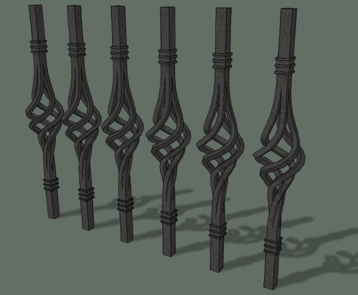
In the comments to my post on drawing twisted spindles, Scott asked about creating a twisted basket for a spindle. I hadn’t thought about this before and I wasn’t quite sure of the best approach but thanks to some help from a few friends and a couple of plugins, I can show a method that works pretty nicely.
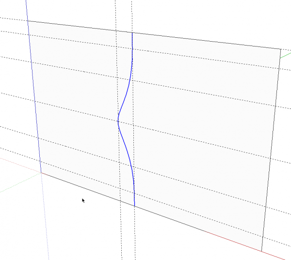
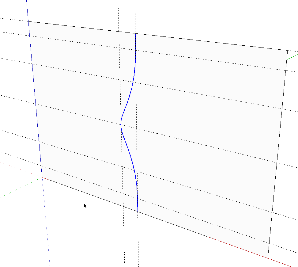
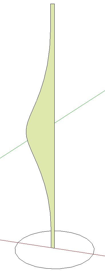
The first challenge is to draw a helical curve for the twist. I used a method similar to the one I described for drawing flame finials. This starts with a profile drawn with a Bezier curve. The top and bottom edges are vertical lines. The Bezier tool is happy to draw a curve in 3D space so to constrain it, I started by drawing a large rectangular face on which to draw. A few guidelines help to shape the curve.
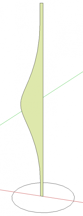
After the curve is completed, I deleted the face and the guide lines. The curve will be the centerline path for an extrusion operation. I’ll use 3/8-in.-square stock for the basket so I set the centerline of the profile at 3/16 in. from the ends of the curve. I welded the curve and straightline segments. Then I drew a circle on the ground plane centered on the center line of the profile.
Here’s an important little detail to keep in mind. The number of sides on the circle must equal or be a multiple of the number of segments in the curve not including the straight segments at the ends. In my example the curve has 20 segments so I made a 20-sided circle. You can check the number of segments in the curve by opening Entity Info and selecting the curve. Change the number of sides on the circle by typing the number and hitting Enter before clicking for the center of the circle. You could also edit the number in Entity Info after drawing the circle.
Now we have a profile and a path for Follow Me.
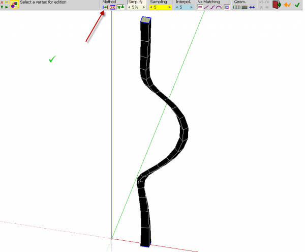
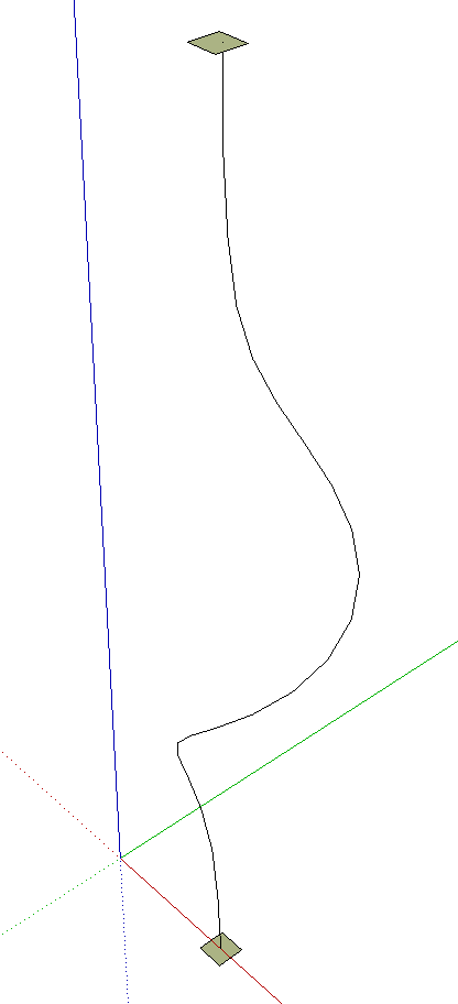
After Follow Me has completed, go to View and turn on Hidden Geometry. Then get the line tool and draw a helix starting at one end and going up diagonally across each small face. I started at the bottom on the red axis. the first and last lines are drawn vertically but the rest twist around the shape.
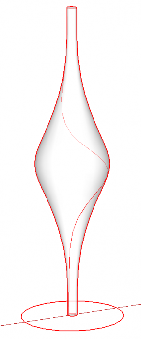
Turn off Hidden Geometry, select the face of the shape and hit Delete. This will leave you with the circles at the ends and a nice helix for the next stepts. Delete the circles and weld the helix.
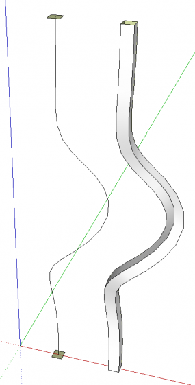
Place a square at each end of the helix. Make sure they have the same orientation. I drew the one at the bottom and made sure it was centered on the helix. Then I copied it up to the top using Move/Copy. Make sure you go up on the blue axis so the copy is also centered on the helix.

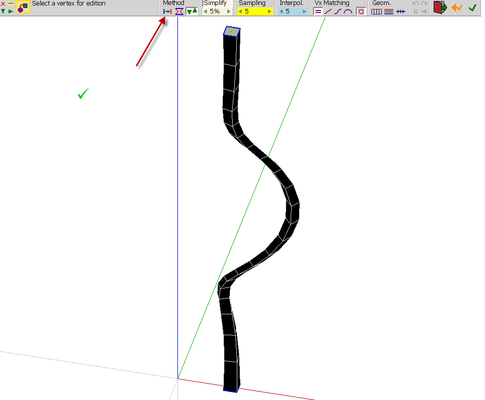
Now select both squares and the helical path and then click the center button ![]() of the Curviloft toolbar. If you hover over the button you’ll get a message that says, “Create loft junctions from a give path.” You’ll get something that looks like this:
of the Curviloft toolbar. If you hover over the button you’ll get a message that says, “Create loft junctions from a give path.” You’ll get something that looks like this:
The shape isn’t right yet. Click on the button indicated by the red arrow in the image above. This “Offsets contours along the rail.” Then click in space or hit Enter.
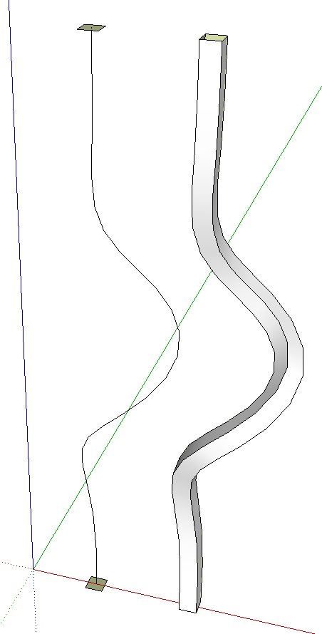
A group is created leaving the original helix and squares alone so they could be reused. If the plugin softens the long edges of the extrusion, open it for editing and triple click on it with Select. Right click and choose Soften/Smooth Edges. I found the proper softening with the slider set to about 26°. Also correct the face orientation if needed. Note: there are no end faces. These could be added by tracing an edge but in my case, they aren’t needed so I didn’t bother.
I prefer to have the extrusion as a component so I closed the group for editing, right clicked and chose Make Component. A Definition Name can then be added in Entity Info.
The twisted extrusion is then Rotate/Copied to make the other three extrusions. then I drew the collars at the top and bottom along with the straigh sections of the spindles. To make the twisted bits look like they are welded together, I turned on Hidden Geometry, I opened the component for editing and hid the edges where the four meet by holding Shift while clicking the edges with the Eraser. I also deleted the internal faces at the ends.
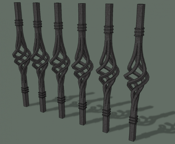
Put a little texture on the geometry and we’re good to go. The basket is separate from the top and bottom portions of the spindles. This would make it easy to mix and match different centers and ends.
Even if you aren’t interested in drawing iron work like this, perhaps you’ll be able to find uses in your own drawing for the process or at least parts of it.


Comments
Hi Dave, I went through the examples you provided with little success. After you used the follow me tool and used the line tool to make the helix I was wondering if you meant the line on surface tool but i still struggled with it, not doing as good as you did. I went with the helix plug-in you used on the twisted spindles and got the results I was looking for and got a fence built with arched gate for a house I'm about finished with. Just the finishing touch I was looking for. So thanks for the posts.
Thanks Walt
Hi Walt,
I did use the Line tool from Tools on Surface but that's not really required. As I think I mentioned in the Flame final post, the ToS Line tool is handy because it doesn't stop drawing when you get to an intersection like the native Line tool does.
Before the method I show here, I tried the Helix plugin but I didn't like the curve I was getting for the path. The Helix plugin will only make a straight taper in one direction and so I attempted to draw half the helix, make a copy, invert the copy and put the two helices together. I got an odd bump where the two joined together and it was too hard to fix.
As long as you were able to get the results you wanted, though, it makes little difference how you arrived at it. i'm glad you gave it a try.
--Dave
Log in or create an account to post a comment.
Sign up Log in