
A reader asked how to make a hinge in SketchUp, specifically a Brusso Stop Hinge (used for small boxes). I’ve created many different types of hinges for my furniture designs, but typically I rough them out without detail, showing overall size only. In the following example, I will create individual hinge halves to enable rotation and positioning.
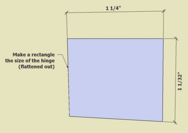
I could not find a dimensioned drawing of this particular Brusso hinge. However, I did find overall dimensions of 1 1/4 x 1 1/32 x 3/16. This hinge has a flat side on the knuckle which provides an automatic stop for rotation.
Step 1: Make a rectangular plate the total size of the flattened-out hinge
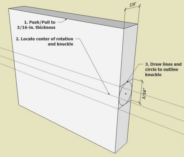
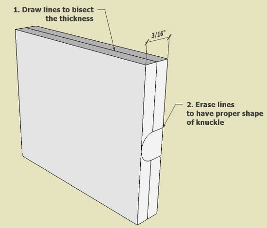
Step 2: Push/Pull the plate to the hinge thickness of 3/16-in. Draw in the diameter and size of the hinge knuckle.
Step 3: Bisect the thickness of the plate by drawing lines around the rectangle. Also use the Eraser Tool to clean up the waste lines for the knuckle shape.

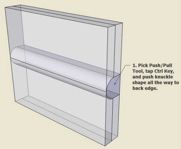
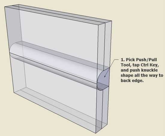
Step 4: Use the Push/Pull Tool and tap the Ctrl Key, then push the knuckle shape all the way through the plate to the other end.
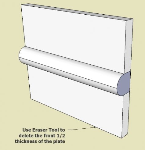
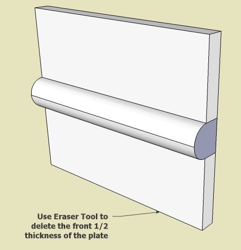
Step 5: Use the Eraser Tool to delete the thickness of the plate.
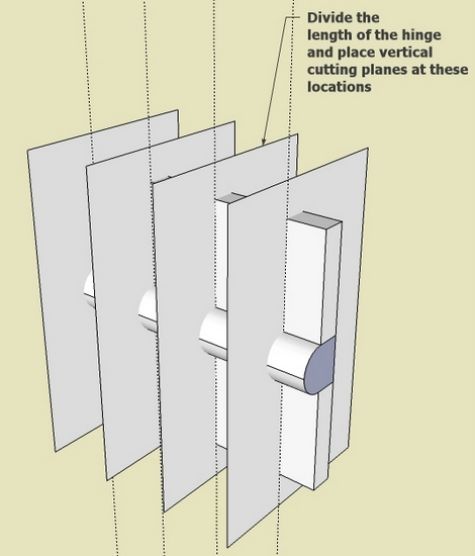
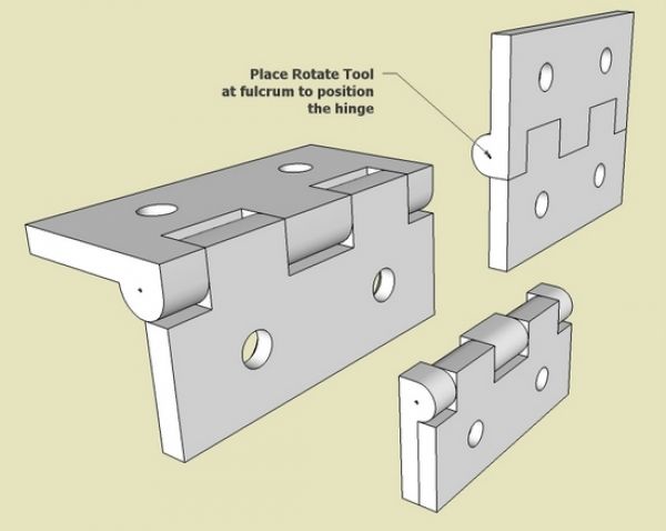
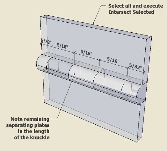
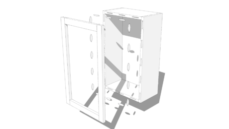
Step 6: The knuckle must be divided up between the upper and lower halves of the hinge. Place planes at the dividing points to use as cutting planes for the knuckle.
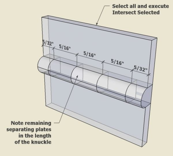
Step 7: Use the Select Tool and draw a select box around all hinge parts. Then right click on the selection and pick Intersect Selected. Use the Erasure Tool to remove unnecessary lines. Now the knuckle is separated into 5 different parts.
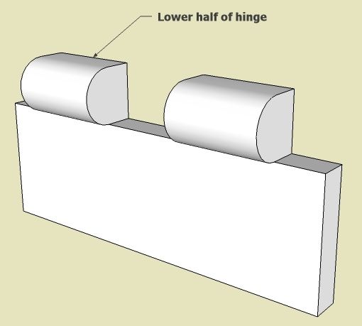
Step 8: Use the Eraser Tool to remove the lower half of the hinge. Make the upper half a component.
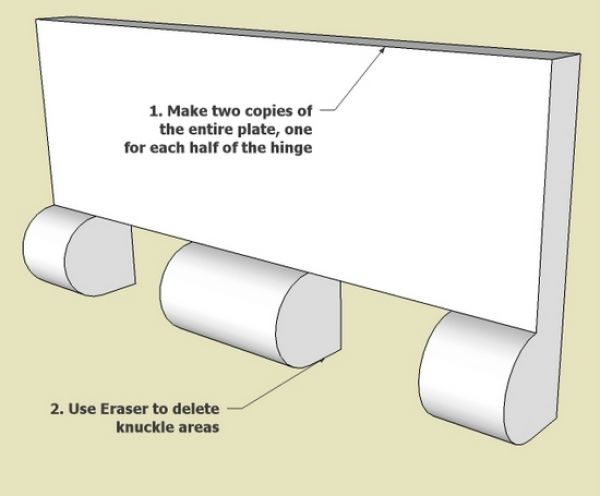
Step 9: Create the lower half of the hinge as well and make it a component.

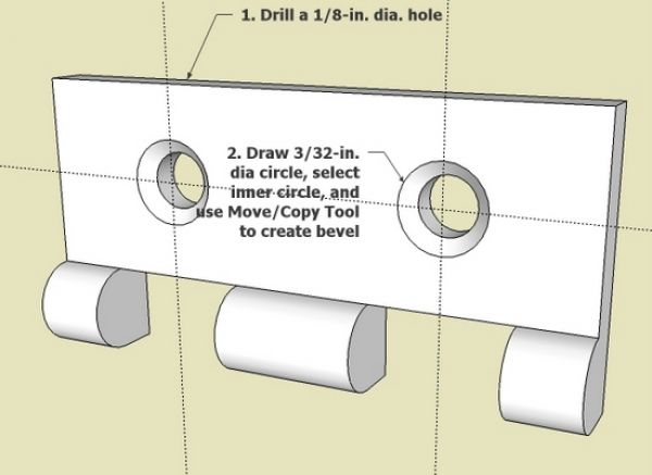
Step 10: Make the screw holes and recess for FHWS.
Step 11: Since each of the halves are components, we can adjust rotation to show different positions of the hinge.
If you would like a copy of the SketchUp file for this hinge, let me know by email.
KJ6APQ


Comments
Hi,
Your SketchUp blog is very interesting.
I would like to look at the file of the hinge, trying to learn how to do...
TIA
Castor
[email protected]
Hi Tim this SketchUp of the hinge is great, is this something you will make out wood or Brass?
Yhanks
Ray
Cataline: At first, I was surprised by your question on whether I would be making the hinge. But then I remembered that my typical blog entry is on something I am actually building. In this unusual case, I have no intention to make the hinge.
Tim
Tim,
Looks so easy when you draw it. I find myself using the "remove material" approach more often as my SU skills improve. Usually easier (for me) to remove material to achieve the shape needed than to add and intersect parts.
Thanks, Larry
Like you I have a background in engineering and I have used a variety of CAD systems including SolidWorks. I started using Sketchup about six weeks ago and I'm loving it. I've done intersecting, usually with planes (rectangle with no depth) because bringing two parts together and hitting intersect seems to give unpredictable results.
The biggest problem I have is assembling two 3-d parts. I've tried using the arrow keys to limit the movement to one axis with some success, but it can be a tedious process requiring reorienting the view to see where the two parts are in relation to each other. Typically I spend as much time assembling completed parts as I spend drawing them.
I've also noticed that some operations (I think the tape rule function for one) sometimes leave a reference line (usually parallel to one of the axis'). Can you use these to drive one part into position with another?
Hopefully Tim doesn't mind me chiming in to answer Tonto's question.
The trick to assembling 3D parts is to use some logic when grabbing one with the Move tool. Grab the component you are moving at a point that will correspond with a point on the other component. You may still need to orient your view differently but you are working in 3D after all.
Tim and I both advocate drawing with the parts assembled in the first place which reduces the need to move components quite so much.
The guideline created with the Tape Measure tool and the Protractor tool could be used as paths for the Move tool if needed. The tool will easily follow the guideline.
Dave
Mr. Richards you have to use “some logic” to even get to first base when trying to assemble to separate parts in Sketchup or to have any success at all for that matter. I consider your answer ridiculous, even insulting. The problem is that frequently, make that almost every time, when you try to drag the first part to the second, Sketchup has difficulty even picking up the the presence second part at all. Obviously you have to select points on both that will be touching each other when placed, how could you do otherwise???
I have extensive experience with 3-D software called SolidWorks that you may not be familiar with, which I used to do machine design. While drawing multiple parts in place maybe an acceptable way to work around Sketchup's weakness in some cases, it is not an acceptable solution (in my opinion) if the parts are many and complex, especially if they are being assembled on single shaft and must be concentric. If SolidWorks performed as poorly when trying to assemble different parts no one would spend the $4,500+ to buy it.
My apologies. I had no intention of being insulting.
I don't know why you are finding that SketchUp doesn't "pick up the presence of the second part." I have never had that happen.
As to assembling components in complex models, building them in place is entirely possible even for parts assembled concentrically on a shaft. If you want to make the parts separately and assemble them afterward, one option would be to place the component axes to give you a desired insertion point. Then you can use guidelines or other references in the model to aid in placing the components.
If you'd like, I would be happy to set up a "live" demonstration with you. Just send me an e-mail by clicking on my name at the end of one of my blog posts.
Dave
Mr. Richards after reading that you have never had the problem I described in my second post I understand why you answered as you did in your first post, so let me apologize for assuming that my problem was experienced by all and taking offense.
I appreciate your kind offer to give me a live demo. I don't think that will be necessary as I understand what you're suggesting, which sounds like a good idea.
Since my last post I fired up Sketchup and drew several simple solid rectangles that I scattered around the work space. I then used the tape rule tool (which you suggested would work) to "measure" the distance between a point on each of two parts that I wanted to conjoin. Doing that left a dotted line between the two points. I then selected one part to move, set the cursor on the "measured" point and was able to drive the one part precisely to the desired point on the second part. I repeated this several times and it worked like a charm and relative to the normal process I've had to go thru, I did it at light speed.
Then I tried pulling one of the rectangles after "measuring" so that the "guide" line entered the side of the target solid rectangle opposite the desired point. When I attempted to drive the first part to the target point, the cursor departed the line when it got to the side of the target rectangle and stayed on its face. It even stayed on the surface of the target when it went around a corner and then went to the desired point. If this continues to work this well, my time to draw will be significantly reduced.
Thank you for your help and again, I apologize for the misunderstanding.
Tonto2, I'm glad you are finding some methods that work for you. There is more that I think you'll find helpful. My next blog post is going to be on the Move tool. I hope you'll check that out.
Dave
Thankyou for your excellent article, Tim. I will follow your method to try to make the hinge ... can you share the sketchup file?
Steve
Steve, I sent you the file I used to create this blog entry. When making the blog I save several scenes so that I can capture each step of the process. Without the blog, you would not need this complexity of scenes. Rather you would do the steps in one place on one instance of the model.
Tim
Tim,
Thank you for this article. I am trying to duplicate it and have been having trouble with the "cutting plane" point. I know there have been several updates to sketchup so not sure if i am missing something. I am using the section plane tool as I couldn't find a cutting plane tool. so I am assuming they are one and the same.
When I put my first plane it it sets that section disappears and so I can never seem to get to the point that you have in your blog with several planes intersecting the model at the same time.
Am I doing something incorrectly?
Thanks for your assistance.
Dave
Dave, a cutting plane and section plane are two different things. The cutting plane Tim refers to is simply a rectangle drawn with either the Rectangle tool or Line tool. Copies of it placed to pass through the hinge "blank" before running the Intersect operation.
-Dave
Thanks, Dave. I really appreciate the quick response. I will give it a go.
Dave Layland
If you need more help, Dave, you can e-mail me by clicking on my name at the end of one of my posts.
Log in or create an account to post a comment.
Sign up Log in