
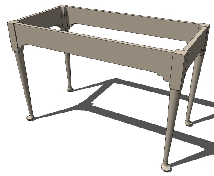
Recently I got an e-mail from one of our readers, Peter, regarding some difficulty he was having drawing a pad-foot leg similar to the one Jon Siegel wrote about in the Jan/Feb 2009 issue of the magazine. I hope some of our other readers might find this useful.
I worked from the article using the layout information provided. I kind of eyballed the profiles for this, though.
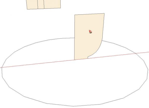
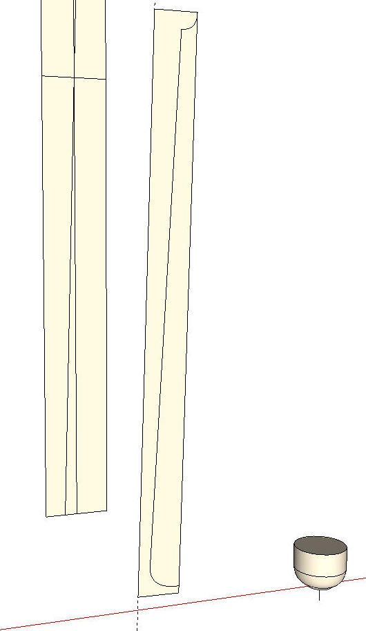
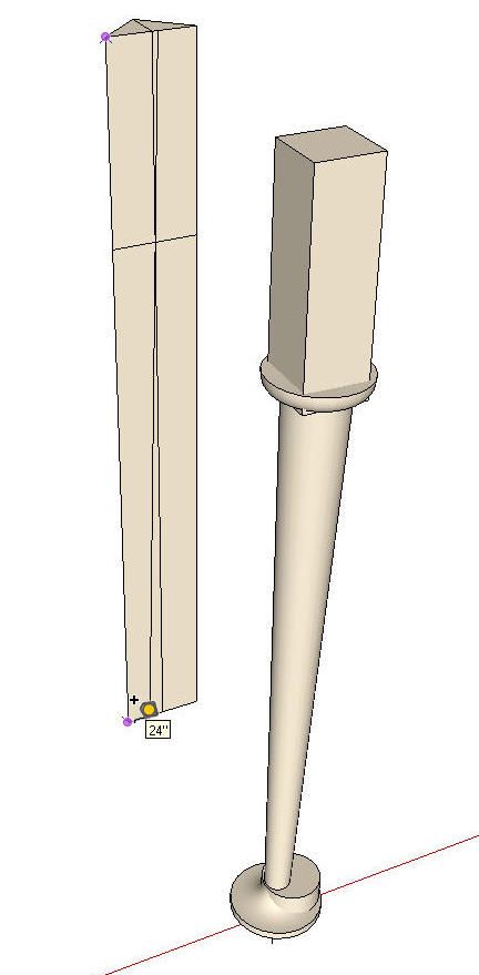
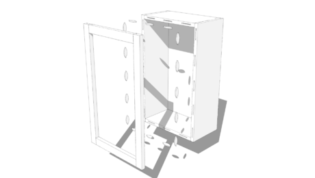
To begin with I made a sort of layout aid. Basically I drew the leg blank, cut it diagonally down the middle and drew in a few lines. There’s a vertical centerline, a horizontal line representing the bottom of the pommel and the angled line representing the centerline for turning the main part of the leg. You’ll see this thing in the background of some of the following images. I used this to pull guidelines from as needed for the various parts. You could think of this as a sort of simple story stick.

For the rest of the drawing I worked centered on the red axis line near the origin. The origin gives me a convenient snap-to point.
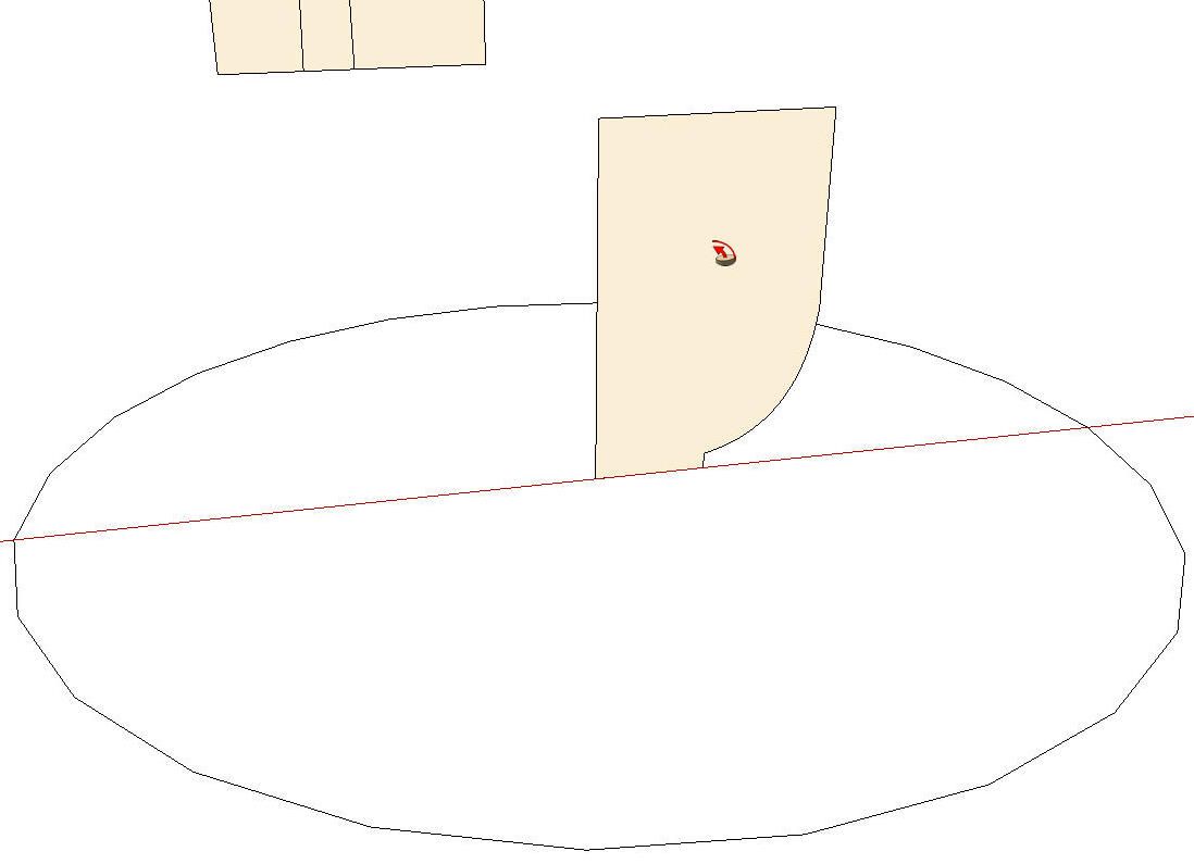
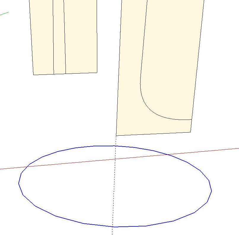
Immediately out in front of the vertical centerline of the story stick I drew the foot profile and a circle to use as a Follow Me path. The profile extends a little above the height where the transition to the leg occurs at the ankle.
I selected the circle to use as the Follow Me path and then got the tool and clicked on the face.
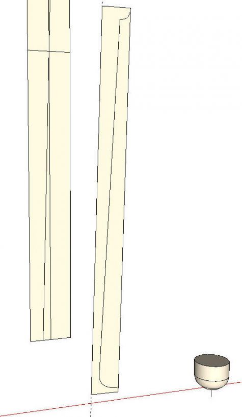
After making the foot, I added a short vertical line at the center to use as a handle later. This isn’t strictly required but sometimes I find it easier to give myself something to grab with the Move tool.. The foot and the handle are made into a component and moved to the side for later use. The circular path is deleted and we move on to the rest of the turned part of the leg.
This time I dragged out a guideline off the angled line on the story stick and worked out the profile based on that. As with the foot, I added a little bit to the profile at the bottom. I also added some for the transition to the pommel at the top. Both of these additions run slightly beyond the finished radius of the turning.
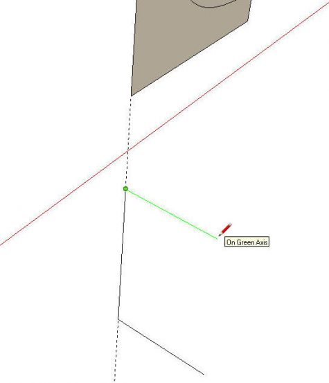
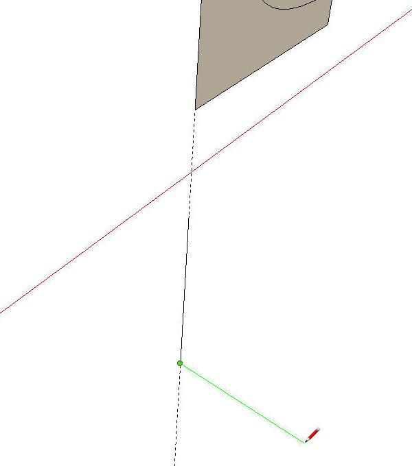
Before running Follow Me for this portion of the leg, we need a circular path with the proper orientation. Here’s one way to get that orientation without too much trouble. First draw a line segment along the guideline on the center of rotation for the turning. the length is not important but don’t connect it to the profile. Then draw a line in the green direction as shown. Again, the length isn’t important.

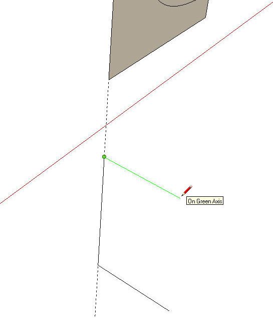
Draw another line segment off the top end of the first segment in the green direction. We could use SketchUp’s inferencing tools to draw a line up, parallel to the first but in this case it is very close to vertical and it’s kind of hard to keep SketchUp from drawing a verttical line instead of a line at the angle we need. Rather than spend time trying to draw the parallel line, I’ll just start a new horizontal line.
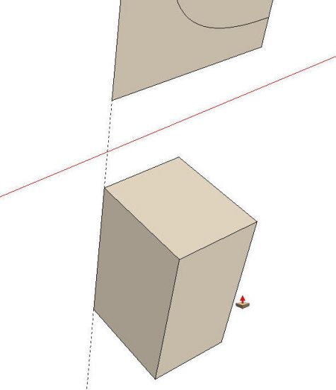
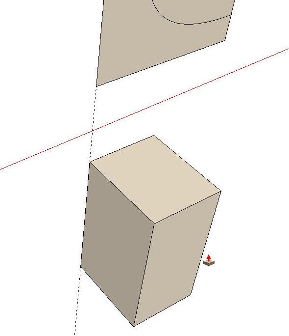
Then complete the face by connecting the ends. Use Push/Pull to create a smnall box. The top face will, by default be perpendicular to the centerline of the turning and we can use this face to get the orientation of the circle before drawing it. The center of the circle will be on the corner where the guideline goes through.
We’ll delete the unneeded part of the profile and then run Follow Me and end up with this.
You can see I’ve added a temproary handle to this turning as well. I made this turning a component, too.
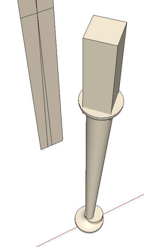
Next we’ll move the foot back into place under the leg. Grab the foot component by the handle and move it along the red axis line. When you get the move going in the right direction, hold the Shift key to lock that direction and then move the cursor to the intersection of the vertical centerline on the story stick and the bottom edge of the story stick. I put in a guideline to show the alignment but you won’t need one to do this.
It’s not looking much like what we’re after but we have a little ways to go. It’s a little like a pecan pie. They don’t go into the oven looking anything like the way they come out.
Now on to the top part of the leg. I use a few guidelines dragged off the story stick to locate the pommel. I drew the square section and pulled it up with Push/Pull. Then I pulled the bottom end of it down a little to ensure a good intersection.
It is easier to draw the pommel aligned to the axes but it really needs to be turned 45° since the toe of the foot is supposed to be oriented that way but is currently parallel to the red axis.
Now we have all of the required parts for the leg but they need to be intersected with each other. Before doing that however, we’ll scale the model up by a factor of 100. This helps prevent little holes in the surfaces due to the dislike SketchUp has for tiny faces. Anytime you are intersecting curved surfaces, there is a potential for these small holes to be created. Scaling up first will head this problem off.
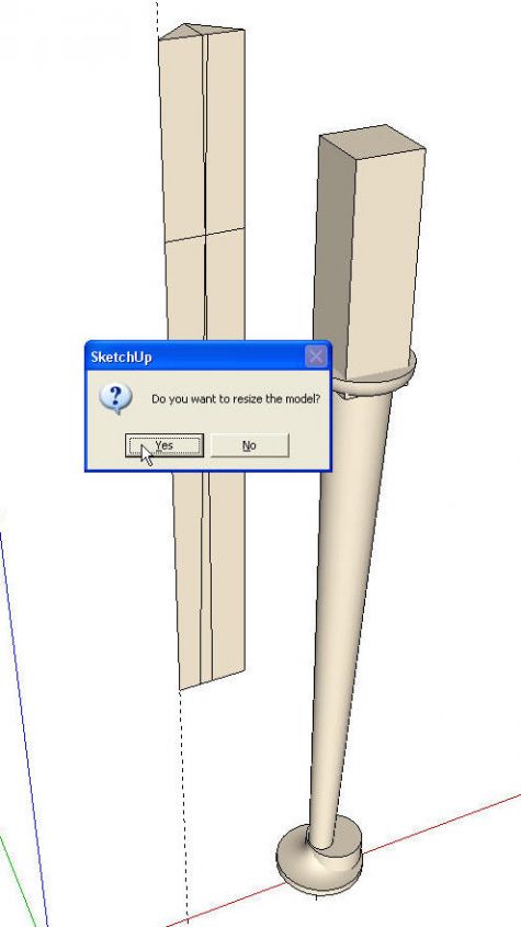
To scale the model up, I used the Tape Meaqsure tool and measured a known distance in the model. In this case it was the vertical edge of the story stick which is 24″ long. I clicked with the Tape Measure tool at both ends of the edge.
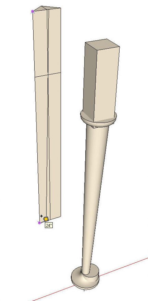
The Dimensions box (AKA VCB) displays 24. I typed 2400 and hit enter. A prompt box comes up asking if you want to resize the model. Click Yes and then Zoom Extents to show the whole model again.
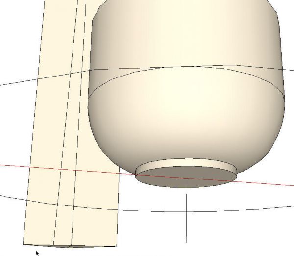
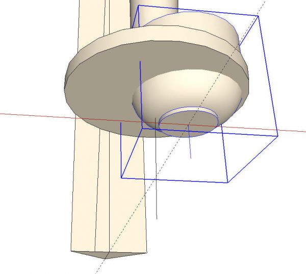
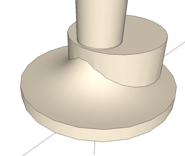
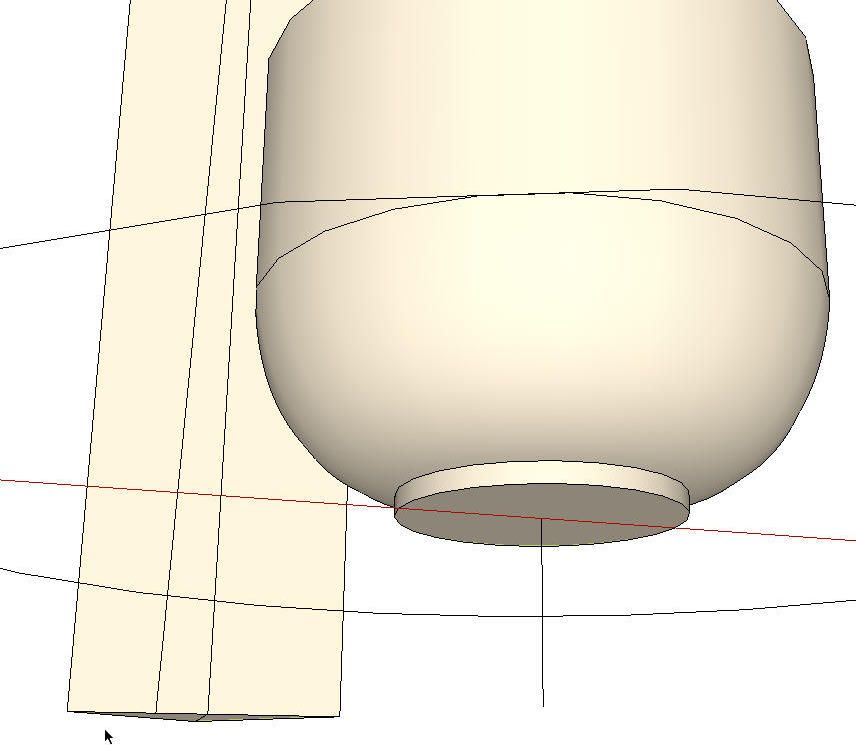
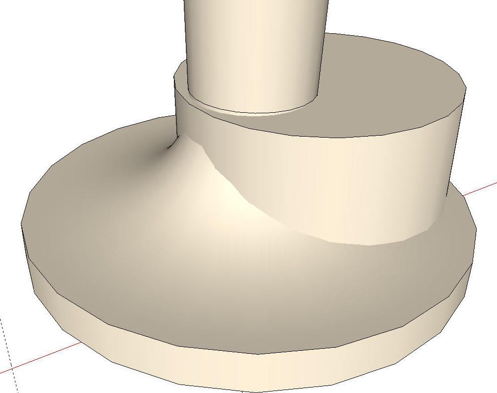
Next we’ll explode the components used to make the turned parts of the leg. You can see where the foot comes up through the flare at the ankle, there’s no black edge. this is becausethere’s no intersection yet.

Select all of the leg geometry, right click and choose Intersect>With Selected. When the inetersection is complete a line will be displayed at the intersection of the surfaces.
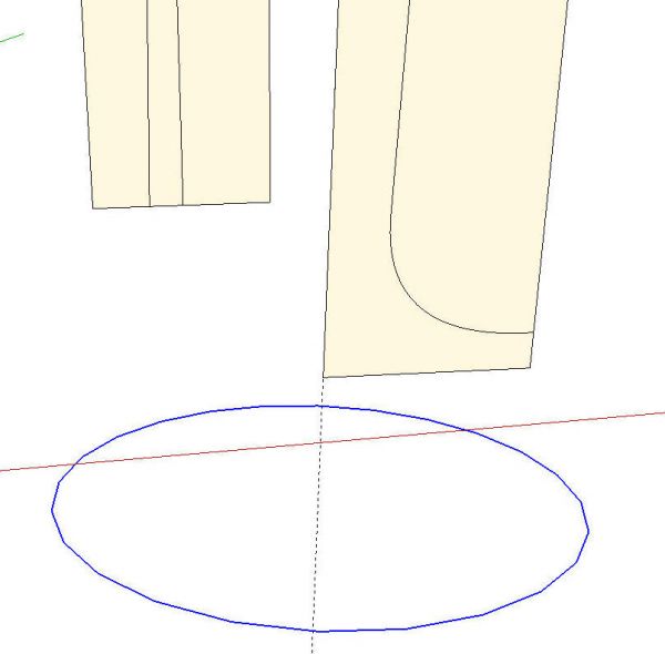
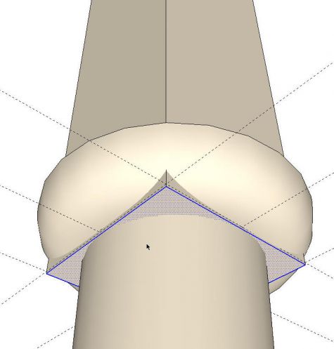
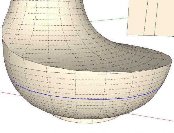
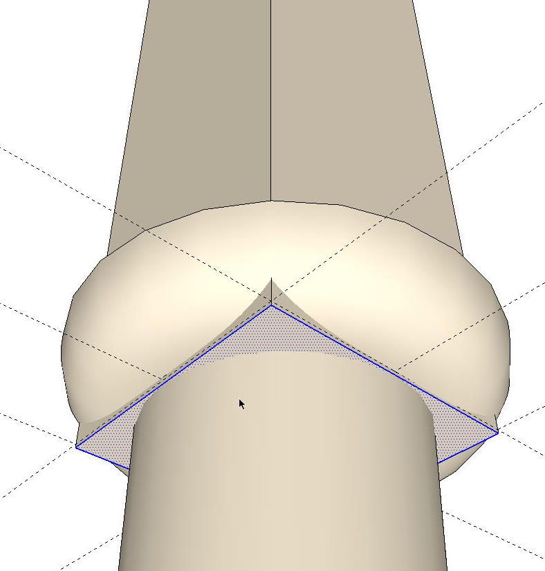
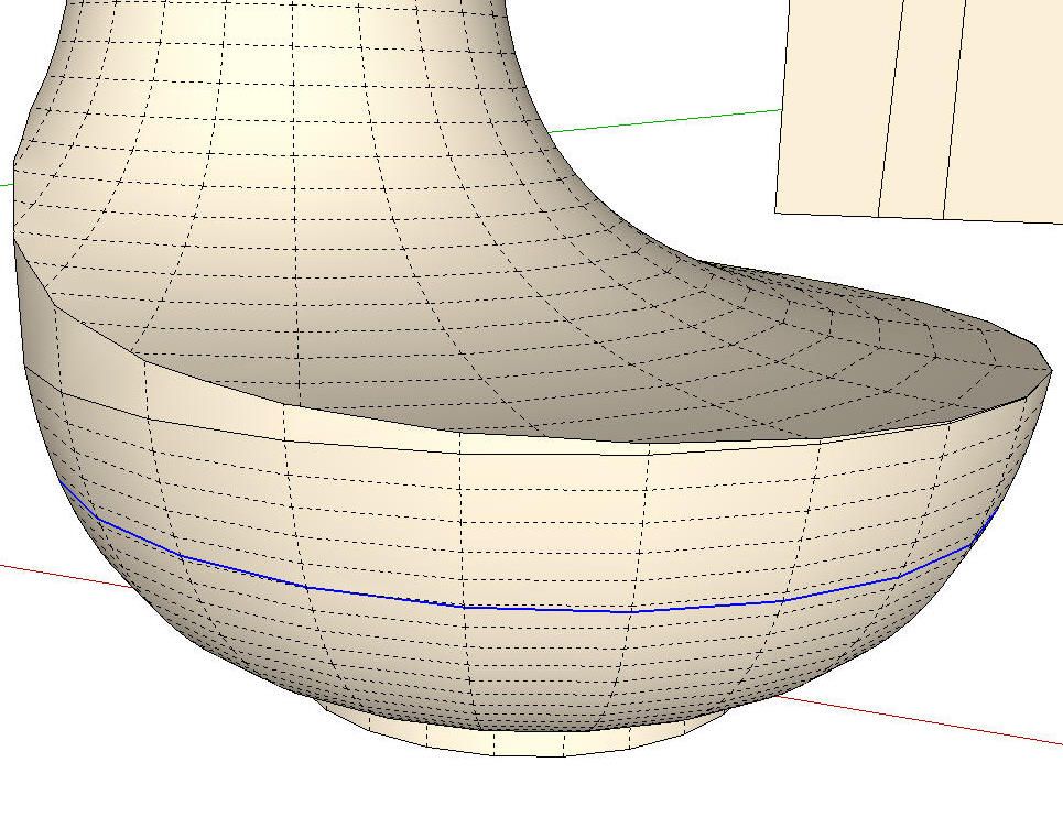
Now it’s time to do some clean up. I like to start by selecting the surfaces I want to get rid of and hitting the Delete key. Then I select loose edges that aren’t needed and delete them. I hunt for coplanar edges such as the ones shown in blue in the next image. Those can be deleted as well. I turned on Hidden Geometry to make it easier to pick out the coplanar edges.
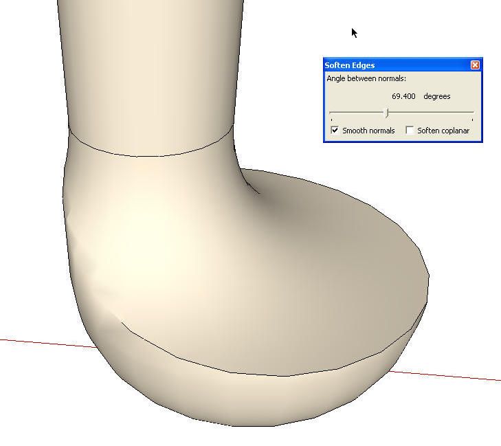
There’s some deleting to do at the top as well and then we’ll soften some edges. Select the leg and right click. Choose Soften/Smooth and adjust the slider as needed. That line around the ankle is a bunch of coplanar edges, too. They should be deleted.

The leg geometry is complete now but the leg is 200 feet tall. We need to make it the proper size before we make it a component. As when sacling it up, I measured the length of the story stick with the Tape Measure and typed 24, Enter. The same prompt box comes up as before and we choose Yes.
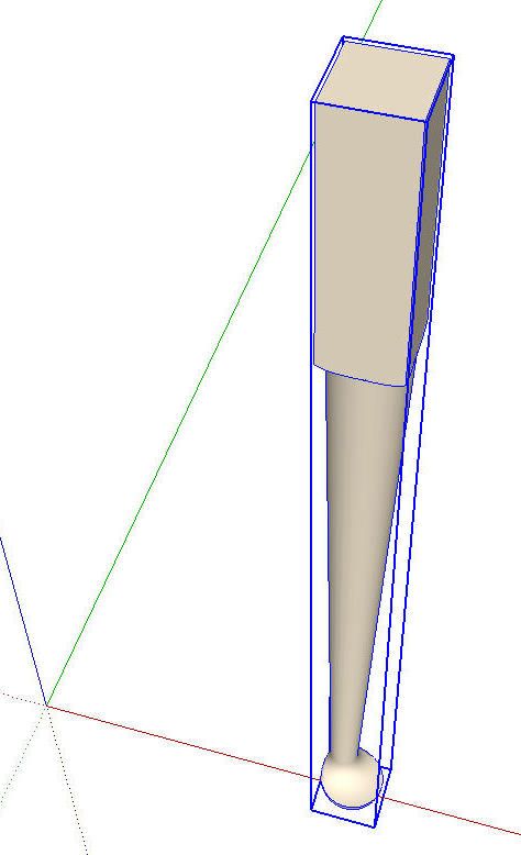
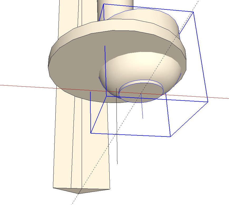
There’s one more thing we need to do before making the component. We’ll rotate the entire leg so the edges at the top are parallel to the green and red axes. This will make it easier to place the leg in a model and if we want to include it in a cutlist, we’ll get the proper size for the blank we’d need to cut. Once the leg is rotated and made into a compnent, there should be a nice tight bounding box around it when it is selected.

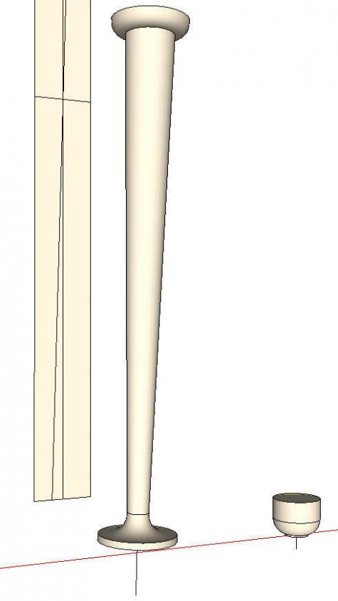
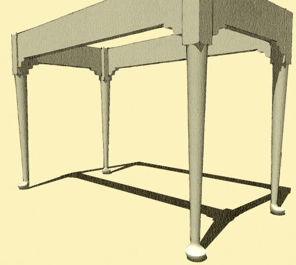
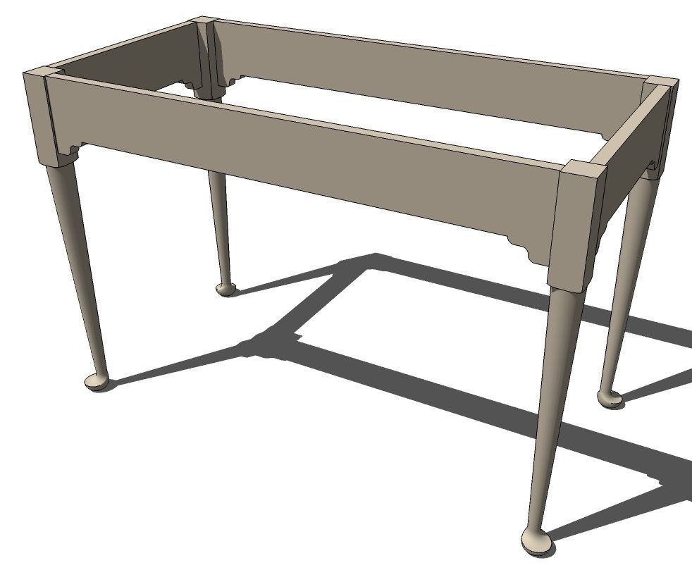
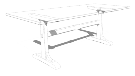
And that’s the leg ready to be used on a table or whatever you wish. You might want to save it by itself for future use so you don’t need to draw it again.


Comments
Handy drawing. How would one actually make a leg like this of wood? I have some possible ideas but what would be your means.
I'd have to buy a lathe first. ;)
It was spelled out in the article I referenced but in a nutshell, there are two centers for turning. One is the vertical axis for the foot. The other is the slightly angled axis for the rest of the leg.
Dave
Thats kinda what I thought. I tried the link to the article but my browser locked up.
What style would this be? Looks spanish/early american
oh never mind i see the federal shaker queen anne tags now.
Hey Dave, is it possible make this pad foot on a cabriole leg using SU. I have spent a lot of time thinking and trying to make it work and still nothing.
Hi Croc, yes, it would be possible to do a similar foot on a cabriole leg. Tim has shown making Cabriole legs using crossing profiles so you would end up with something similar to what you would get after cutting the leg out on the bandsaw on two faces. Another option would be to use Follow Me on the leg profile with the path drawn so you create the outside shape of the leg. Then do another follow me operation for the inner profile of the leg and intersect those two shapes. The foot itself could be done much as I did it here and added to the rest of the leg.
I hope that makes some sense. I'll try to get a demo done one of these days soon.
Dave
Thanks Dave, I understand how to make the bandsaw leg but I don't quite follow your explanation regarding the follow me tool. A demo would be very helpful and much appreciated if you would be so kind.
Log in or create an account to post a comment.
Sign up Log in