
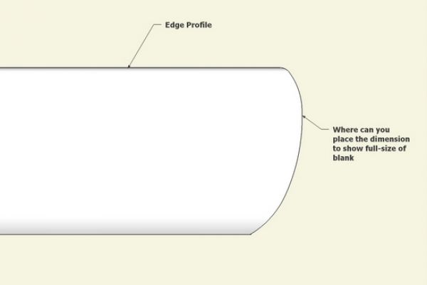
Occasionally I’m faced with components which are hard to dimension; for example, when the component has a fully shaped edge and I can’t easily find the endpoints to place a dimension. The Dimension Tool won’t snap on the curved surface and I’m not sure where to connect the dimension to indicate full length, width, or thickness of the component.
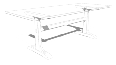
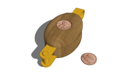
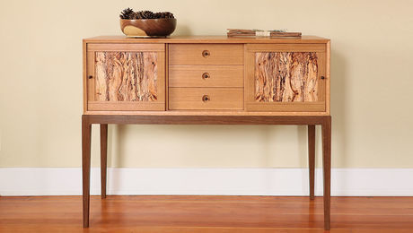
Here is an example where the top of a case piece has a rounded shaped edge. Also I’ve shown below a close-up view of that edge shape. Where is the outer edge point to snap the Dimension Tool?

There are probably many ways to help with this dilemma of placing the dimension, but here is one way that I’ve found useful:
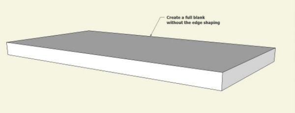
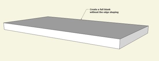
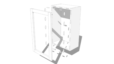
Step 1: Make the full size of the blank without the edge treatment. Or save the initial blank before you run the Follow me Tool which creates the edge shape.
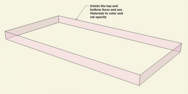
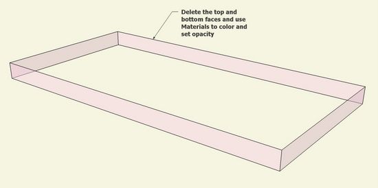
Step 2: Delete the top and bottom faces, leaving only the square frame. Also use the Materials dialog box to color the frame and make it transparent. In the Materials dialog box, there is a small + icon to make a material. This will provide a slide bar setting for the amount of desired transparency. Once the new material is made, you can “paint” the material on the four faces of the frame.
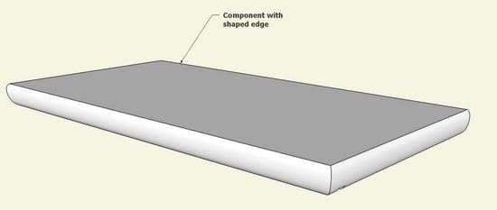
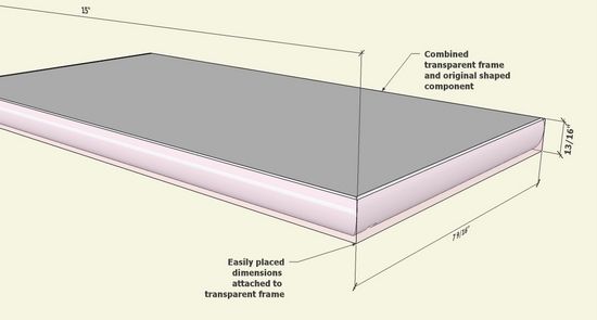
Step 3: With the Move/Copy Tool, place the transparent frame exactly into position over the shaped component. Now you have a convenient frame for showing the blank dimensions in the drawing package to take to the shop.


Comments
Would this as well?
1. Draw a line through the component on the blue axis and close to the edge but through the full thickness of the component.
2. Draw a dimension using the intersect of the line and each face.
3. Delete the line leaving the dimension in place.
To robscaffe: Yes that would work fine. However, I must admit finding it worrying upon seeing a dimension hanging out in mid air not connecting to anything.
Tim
A trick I've used a few times is to place a guide line or two in the relevant places and the dimension will stick to the intersections created. Once you have the dimensions marked you can delete the guides.
Obviously this has a deficiency in that altering the dimensions of your piece will not affect these 'orphan' dimensions but you can't have everything.
Another option is to temporarily make hidden geomtry visible (View menu) and apply the dimension to either the longest hidden edge or between edges as appropriate. The dimension will still be visible when the geometry is hidden again and it will update with changes to the component.
Log in or create an account to post a comment.
Sign up Log in