
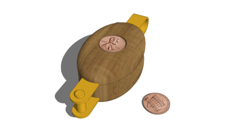
My last blog entry set the stage for building this Knife Box, one that was presented at the January Williamsburg conference “Working Wood in the 18th Century”. This video is second in the series covering the initial steps in creating the SketchUp model.
The compound angles of the box make the modeling work more challenging. The tracing process over a photograph image produces flat faces that are orthographic. In other words, the traced faces are projections of the real splayed out components. The projection does not represent the full width of the component when in the splayed position. Therefore, there is some extra work to find the real width of the side and end components.
The 3D modeling also uncovers an issue at the corner joints; that the parts are too short to fully overlap. So the End and Side components need to be extended in length slightly to ensure a full overlap for the future dovetail joinery.
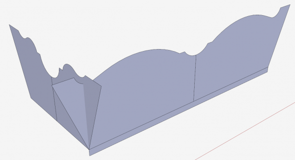
Screen 1: The traced over shapes positioned on the Box base. Note no splay.
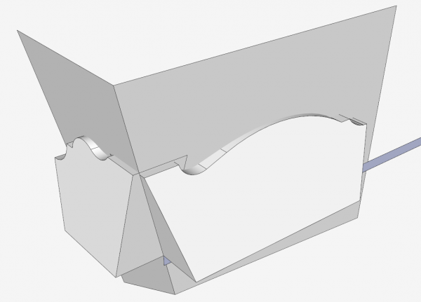
Screen 2: My method shown in the following video for finding the real size of the splayed End and Side components. First step is pulling out the shapes to overlap in the corner. Then making faces at the splayed compound angle.
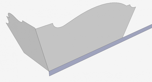
Screen 3: Using the Intersection feature, and removing the waste shows components at the correct splay and size.
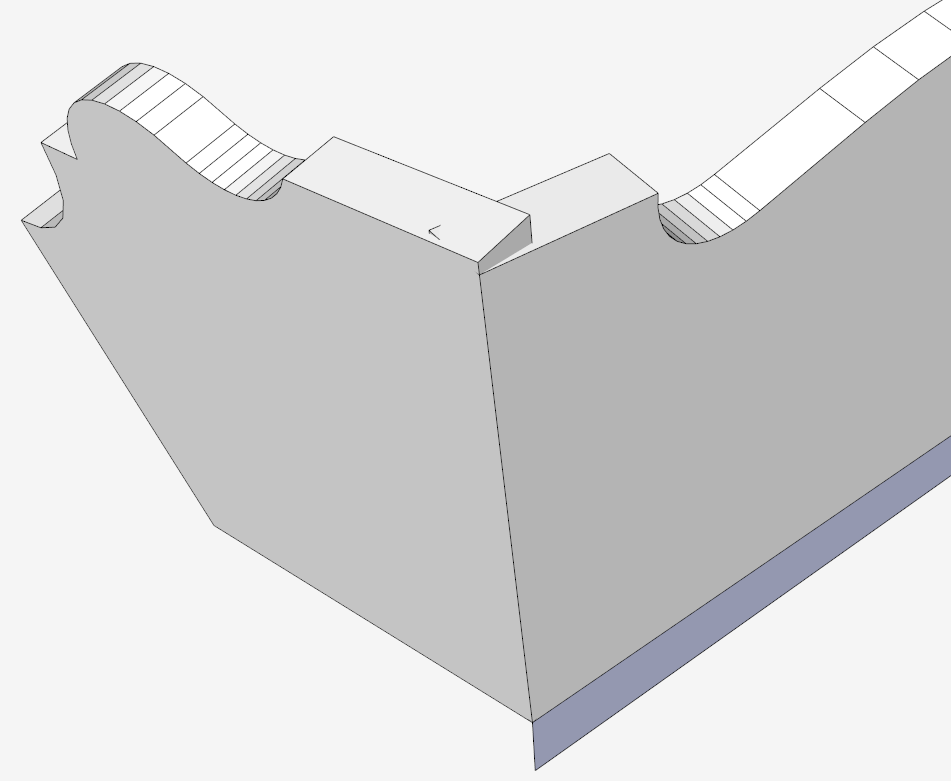
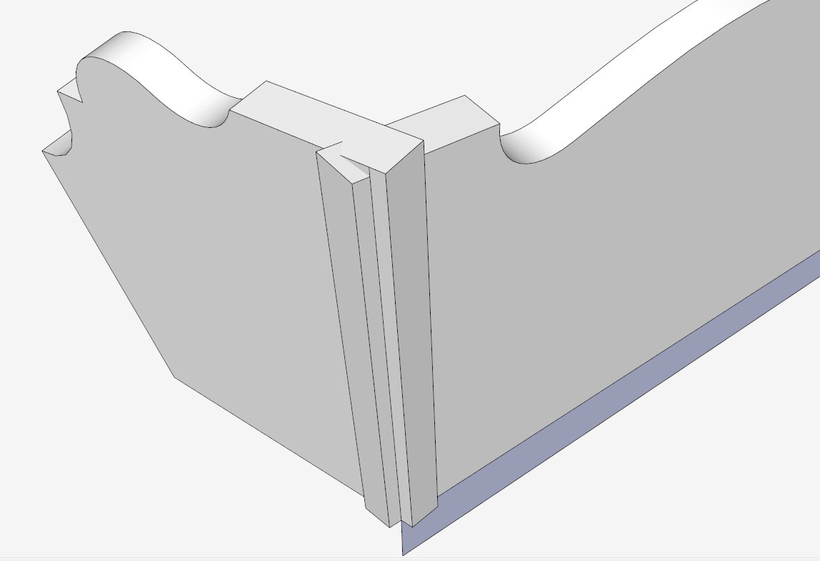
Screen 4: Close-up view of the corner, showing the issue that the components do not fully overlap at the corner.

Screen 5: Increasing the length of each component to ensure adequate overlap. These extended lengths are required for milling of blank pieces in the shop.

Here is the 12 minute video.


Comments
Tim,
Nice, clear video. One question, however: Why make the side and end shapes groups at first? Why not make them components?
David5346: Good catch and comment. One reason I use Groups at first before changing to Components, is the process of tracing over faces in the imported image. If I make these shapes components on the tracing, later changes to the components ruin my initial shapes. I like to retain my initial shapes since they are valuable assets to use again.
When I'm doing a design for the first time, I find that I'm experimenting with alternate ways of creating components, some of which will be discarded, I find that using groups in this early stage of figuring out the component, makes it easier to have multiple trial runs, saving each one, and allowing my returning to any of these alternates.
Nonetheless, when I am done experimenting, and before using multiple instances, I switch to components.
Tim
Great technique you have got there. Thanks for sharing the video with us all. The design of the box definitely look complicated and intricate but with step-by-step guidelines like these, I think it is indeed possible. I have a few ideas of some other patterned boxes as well which I was afraid to experiment out initially. I guess with determination and some research, nothing is quite impossible. I love engaging my friends and family with such projects as I believe in family bonding that just gets everyone together doing something interesting and spending quality time together.
Audrey Greenwood. Interesting that you would mention family projects. Throughout my life our family shared and collaborated on art, sewing, and woodworking projects. We are planning a get-together later this year and already planning the projects that will be a product of the visit. These may likely include Shaker Oval Boxes and quilts.
Tim
Log in or create an account to post a comment.
Sign up Log in