
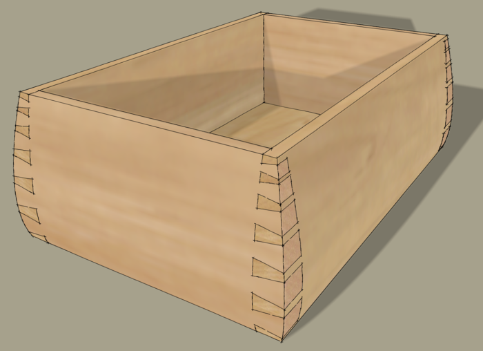
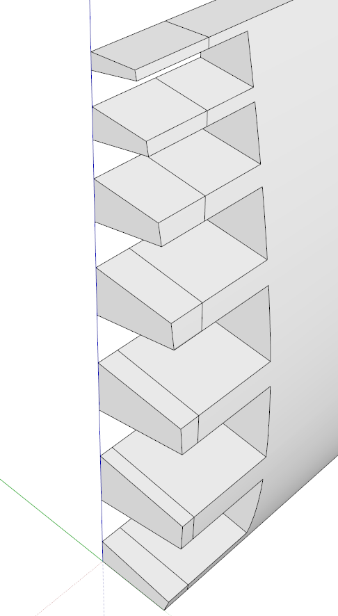
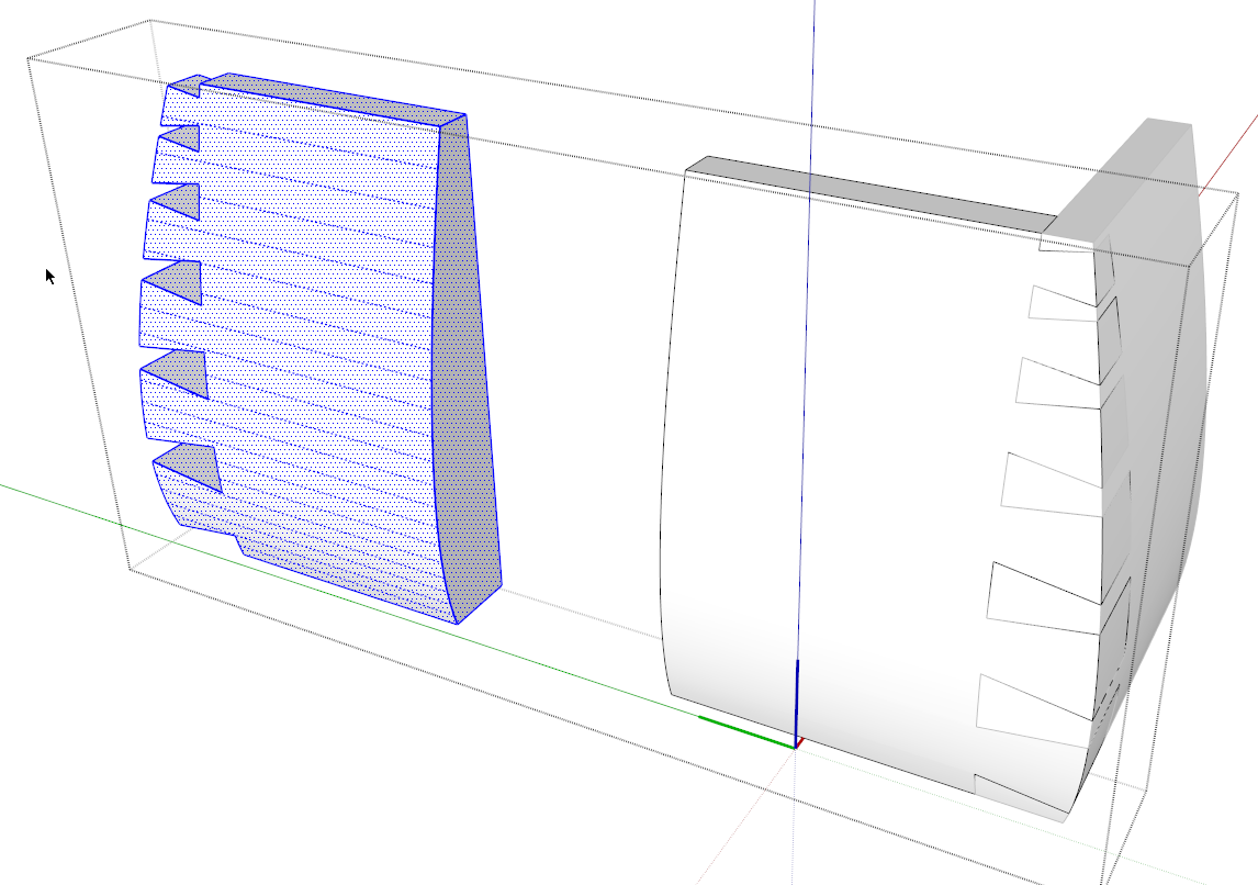
A friend and reader of the blog sent me an e-mail the other day asking me how I would go about drawing dovetails similar to the ones I’ve got here.
The pins and spacing between them are graduated and the outside faces of the box are curved. I can think of several ways to lay them out as well as to cut them. Here’s one of them.
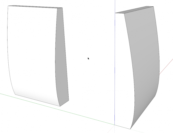
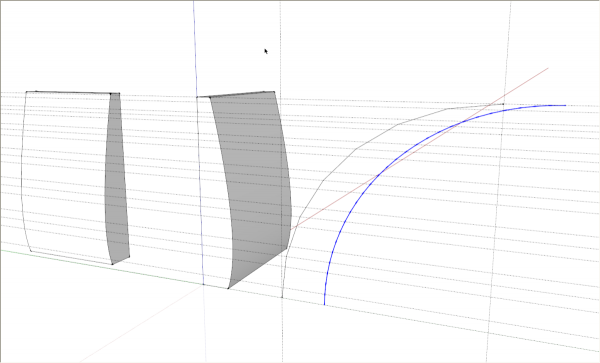
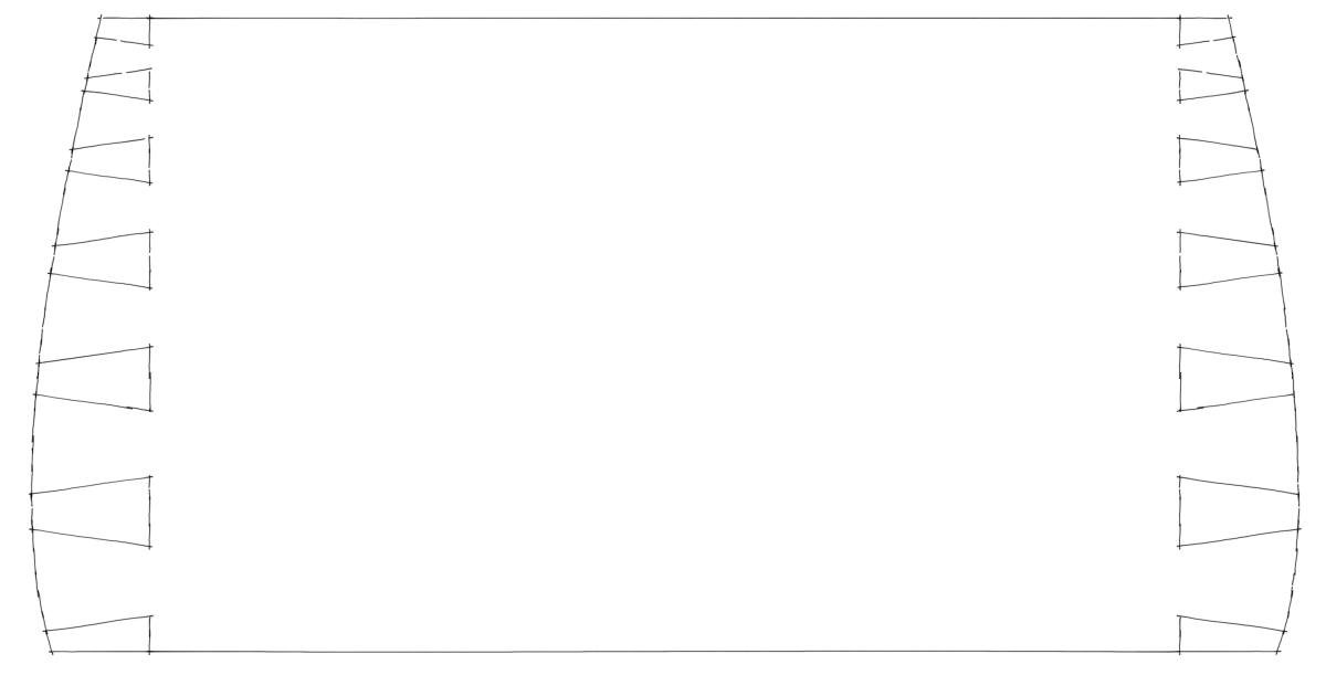
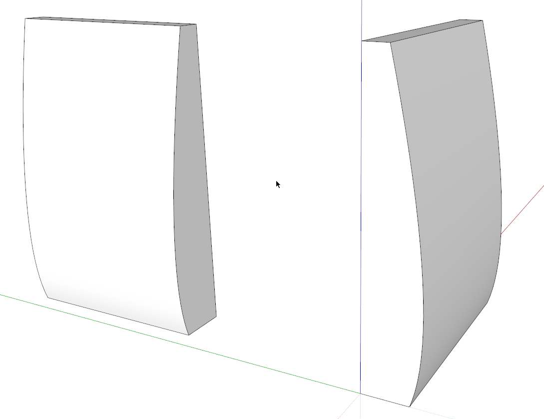
I started with a couple of components with the curve drawn. These will be the adjoining sides of the box but they don’t need to be the full length of the final sides.
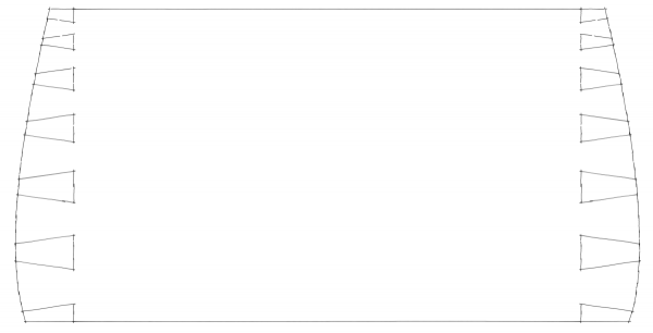
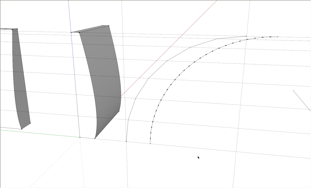
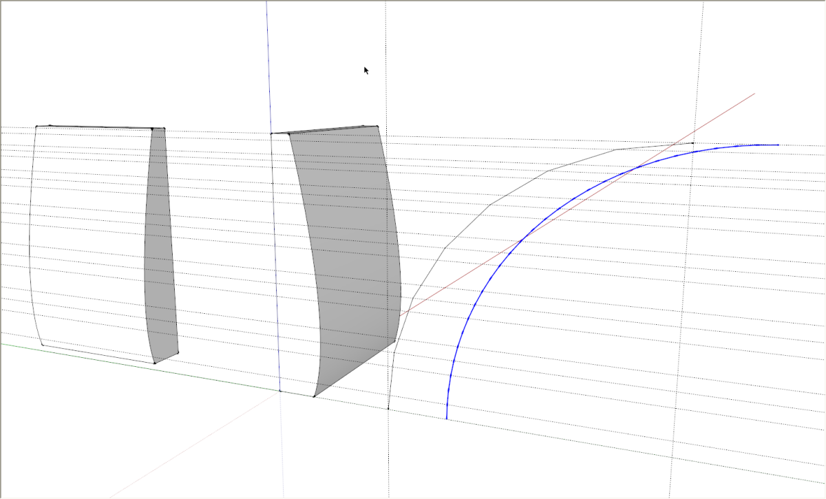
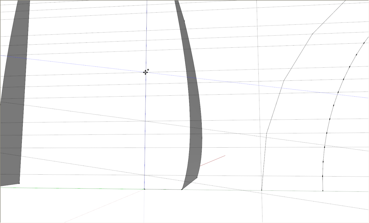
To create the spacing I drew a quarter-circle arc with seven segments. The vertices were used to identify the rough centers of the pins. I actually played with the number of segments on the arc until I got a pleasing arrangement. You can shange the number of segments in the arc via the Entity Info box found under the Window menu. I then put in horizontal guidelines using the yellow Taple Measure too. Then I changed the number of segments to 28 segments. I added a second arc to show that for this tutorial but you can just change the number of segments in the original arc.
I used the vertices on either side of the center lines to definie the overall width of the pins.
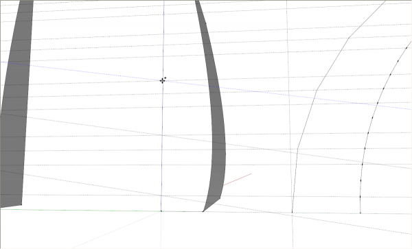
Next, using the yellow Protractor tool, I set in angled lines for the pins. After placing the first angled line, it can be copied with Move+Ctrl (Move+Option on Mac).
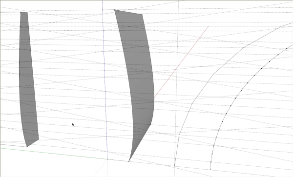
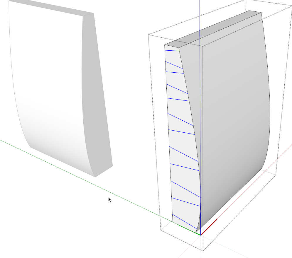
There’s quite a spider’s web with all those guidelines in place. Next trace the angled guidelines with the Line tool.
I selected the lines and used Edit>Cut (Ctrl+X) to cut the lines. then I opened the component for editing and used Edit>Paste in Place to get the lines into the component that will receive the pins. Also paste a copy of the lines off to one side for later. (not shown)
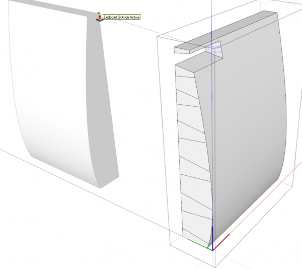
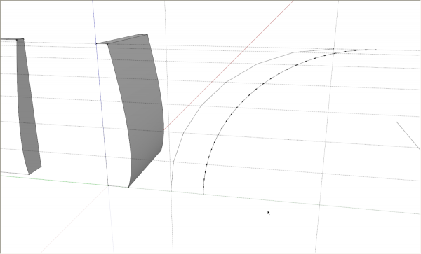
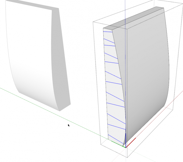
Push/Pull makes quick work of creating the pins. Now we need to trim the ends of the pins to match the side.
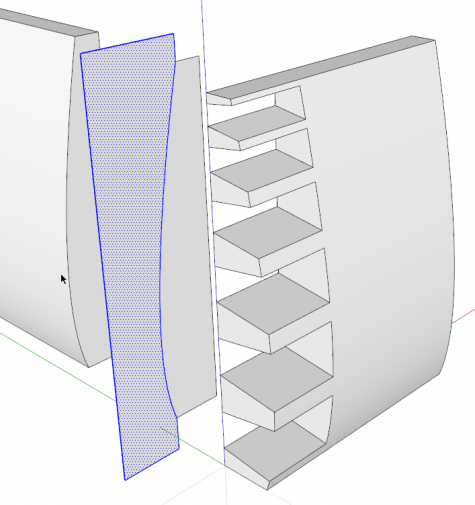
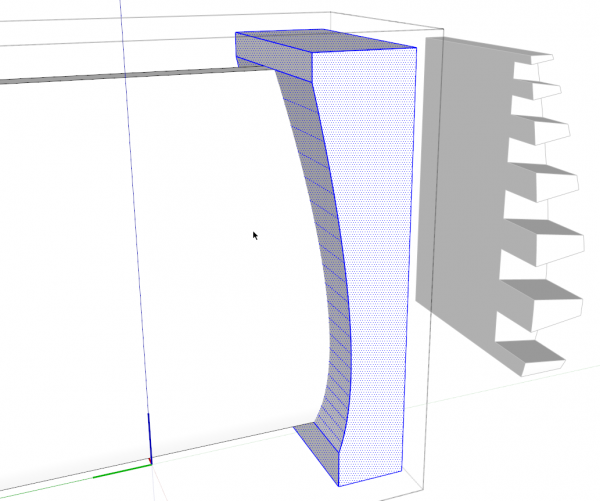
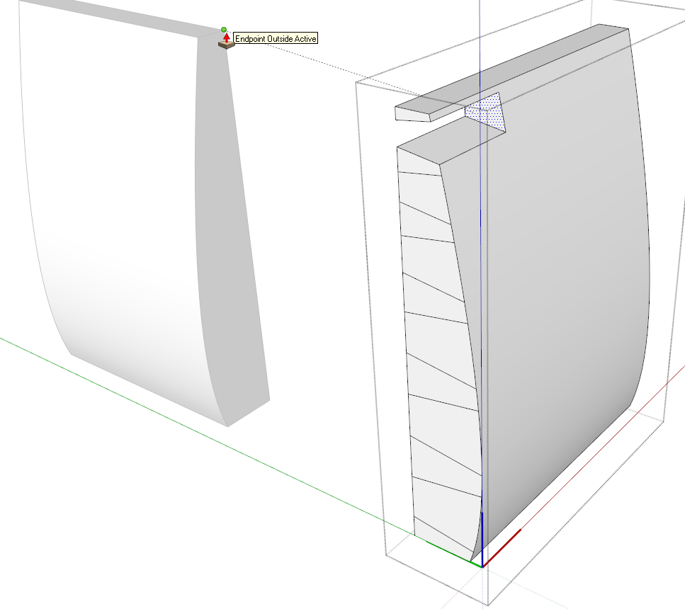
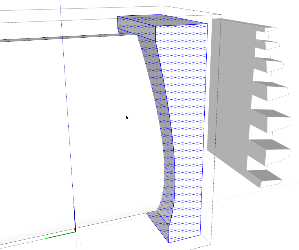
I copied the face off the end of the other compoent and then drew the face shown selected, above. Imagine this is the shape of a large shaper cutter.
I extruded this shape though the pins. This was done outside the component to avoid potentially deforming the pins before I was ready. Then I selected the cutting shape, used Edit>Cut, opened the component and used Edit>Paste in Place. Then I selected all of the geometry and used Intersect Faces>With Selection.
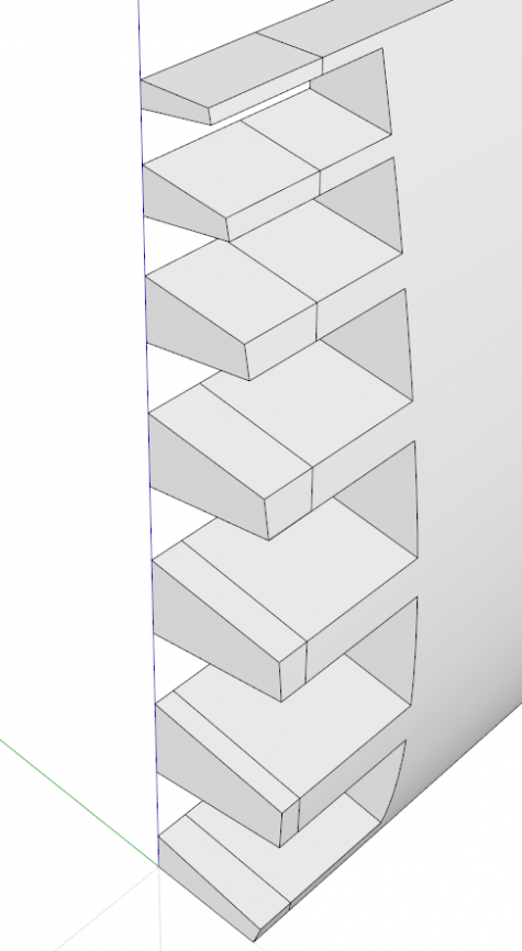
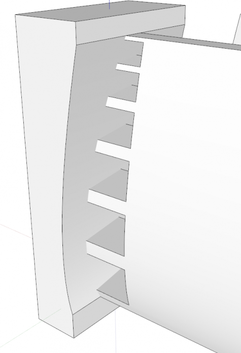
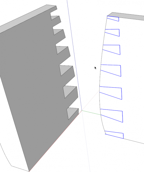
After deleting the cutter, you can see that the pines are cut. Delete the edges outboard of the cut lines and correct face orientation as needed.
Since the curves on both sides of this box are the same, I opened the other side component and pasted the cutting shape–it was still on the clipboard–and used it to trim the end of the side.
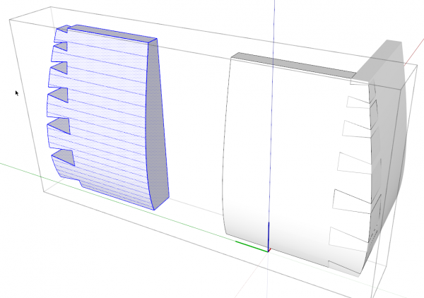
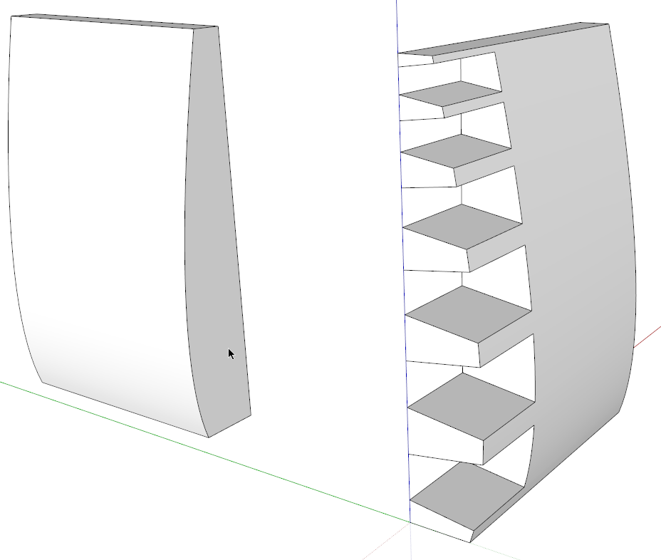
I made another copy of the pin layout and pasted it on the inside face of the second side component. As before, I placed these lines outside the component. then I used Edit>Cut, opened the component for editing and then used Edt>Paste in Place to get the lines onto the face in the component.

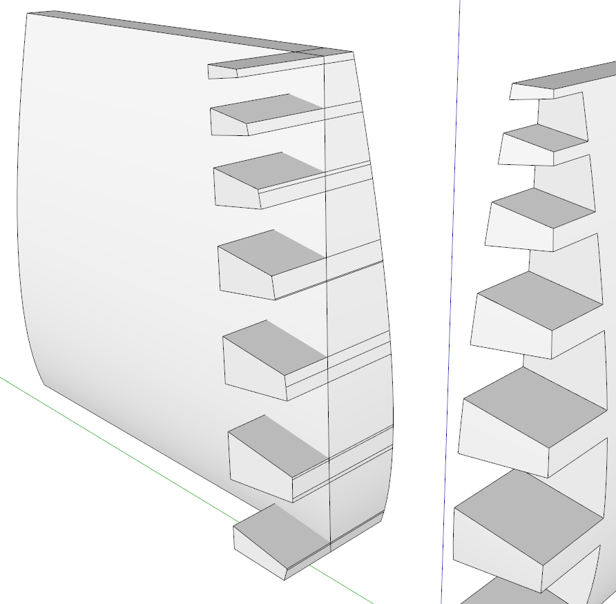
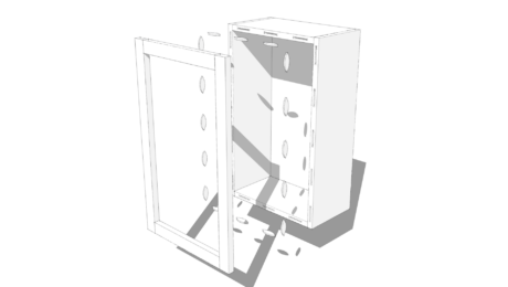
With the component still open for editing, I used Ctrl+Push/Pull to push the pins through the side. This doesn’t leave the sockets we need but if you try to use Push/Pull without Ctrl, it won’t let you push the faces through the curved surface. After completing the Push/Pull operation, select all the geometry and run Intersect Faces>With Selection. Delete the waste and correct the face orientation as needed. This will complete the sockets for this end.
To make the opposite end of the side, open the component for editing. Select all of the geometry–a triple click of the Select tool makes quick work of it. Use Ctrl+Move to copy the geometry down along the green axis in this case. Then, while the copy of the geometry is selected, right click on it and choose Flip Along and in my example I chose Green Direction. After that, place this copy as needed for the overall length of the box. Use Push/Pull to join the two ends of the side and delete the seam line in the middle.
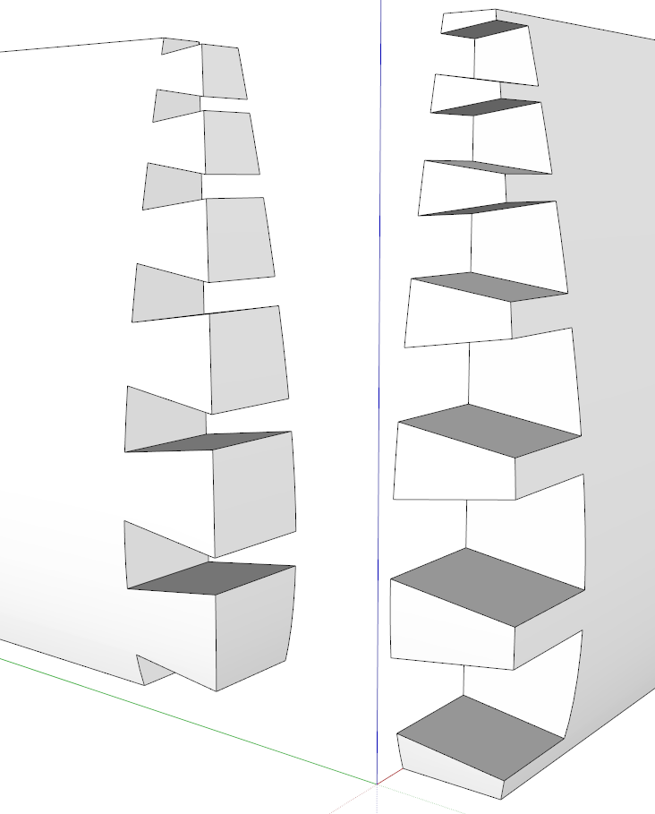
Repeat that process for the other side of the box.
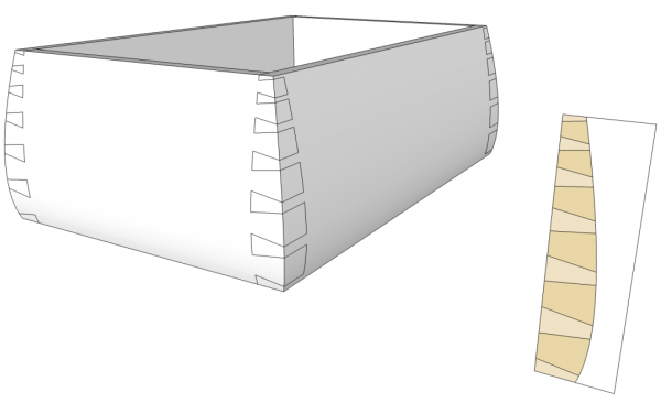
Copy and flip the sides to make the other two sides of the box and put them in place. If you used the same lines for cutting the pins and the sockets, everything should fit without any gaps. If you want to create a template from this layout, make sure you’ve saved a copy of the layout lines. This can then be printed at 1:1 and used directly on the wood when you get to the shop.
This seems like a long process although it moves right along if you work in a methodical way. That said, the first time I drew these dovetails I used Trim from the Solid tools which is a tool in the pro version of sketchUp. It probably took me about a quarter of the time it took me to do the trimming using Intersect Faces and deleting the waste.


Comments
Nice one, again, Dave, thanks! I like your dovetail layout trick.
I'm wondering about when it comes to implementation. Do you cut the dovetails before or after shaping the curved face?
I guess I would cut them before shaping the surfaces. They'd be easier to lay out that way. And if you were so inclined, you could print out full sized templates to apply to the stock so your lay out is automatically done.
-Dave
Log in or create an account to post a comment.
Sign up Log in