
I had an e-mail today from a reader who is interested in using SketchUp for laying out kitchen cabinets. He was asking for suggestions on how to make this an efficient task. He also wants to be able to create a cutlist from the components in the model. Here are some suggestions for an approach that will make laying out kitchen cabinets an easy job.
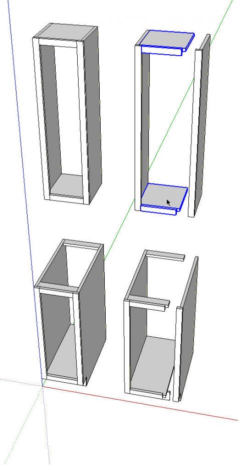
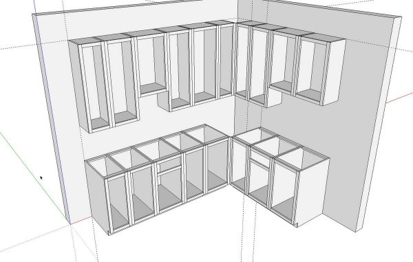
We’ll need a library of components to use in our kitchens. I’ve started by drawing simple upper and base cabinets. I began with standard 12 inch wide cabinets. Since a detailed cutlist is one of the goals, I’ve drawn all the parts we’d make in the shop as individual components. Of course I’ve copied and flipped components that have mirrored counterparts such as the case sides and face frame stiles. All of the components which have dimensions that are determined by the case width get Definition Names that reflect the case width. This will make them easy to identify in the cutlist. Parts such as the case sides and face frame stiles will be the same from cabinet to cabinet so they don’t need special names. On the upper cases, there are different standard heights so you’ll want to take that into consideration when naming those parts.
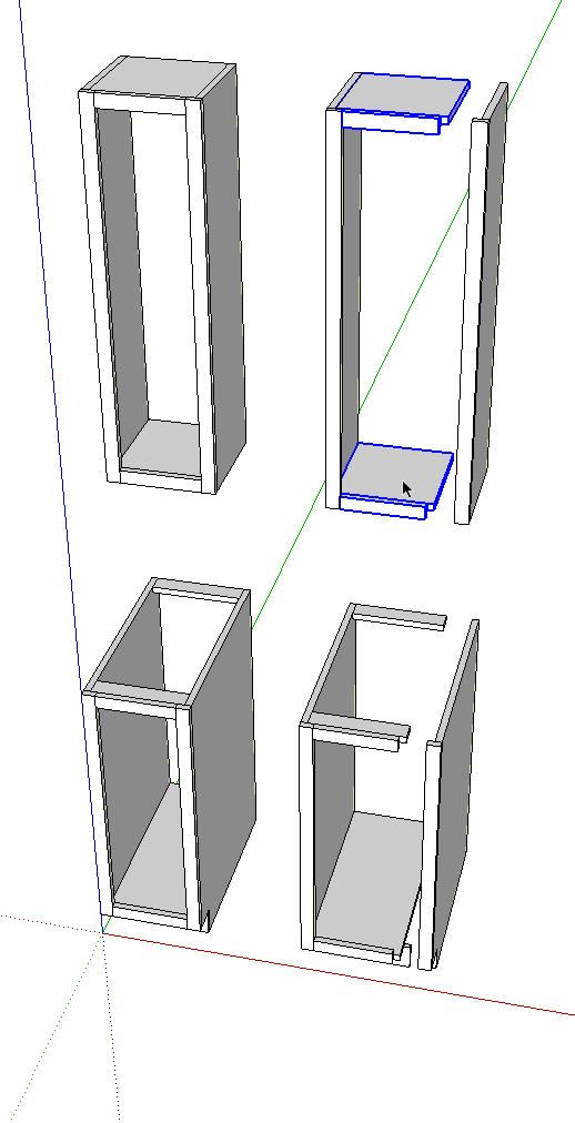
After making the initial upper and base cabinets, copy them over to the side a little bit with Ctrl+Move. In the image above I’ve moved the right hand case sides and face frame stiles to the right 3 inches with Move. Select the horizontal components in these copies of the cabinets (I show the components in the upper cabinet selected), right click and choose Make Unique. This will break the relationship of those components with those in the original cabinets.
I didn’t show it here but before moving on to the next cabinet make the current cabinet a component and set it up to glue to vertical surfaces. I’ll show how to do this with the doors because they’ll get the same treatment. When you set up the gluing plane you’ll also be setting the component origin location which defines the insertion point. Decide how you want to insert the components in your model. I opted for the top rear left corner on the uppers and the bottom rear left corner on the base cabinets. You can put those points where ever it makes sense. Consider how you’ll want to add them to a kitchen drawing. All of the cabinets will have corresponding insertion points. After placing the left hand cabinet in my runs I can insert subsequent cabinets by clicking on the appropriate right rear corner on last cabinet I placed. You might prefer to work from the right or perhaps you want to work from the centers although that will require determining the location of the center of each cabinet relative to the rest of them.
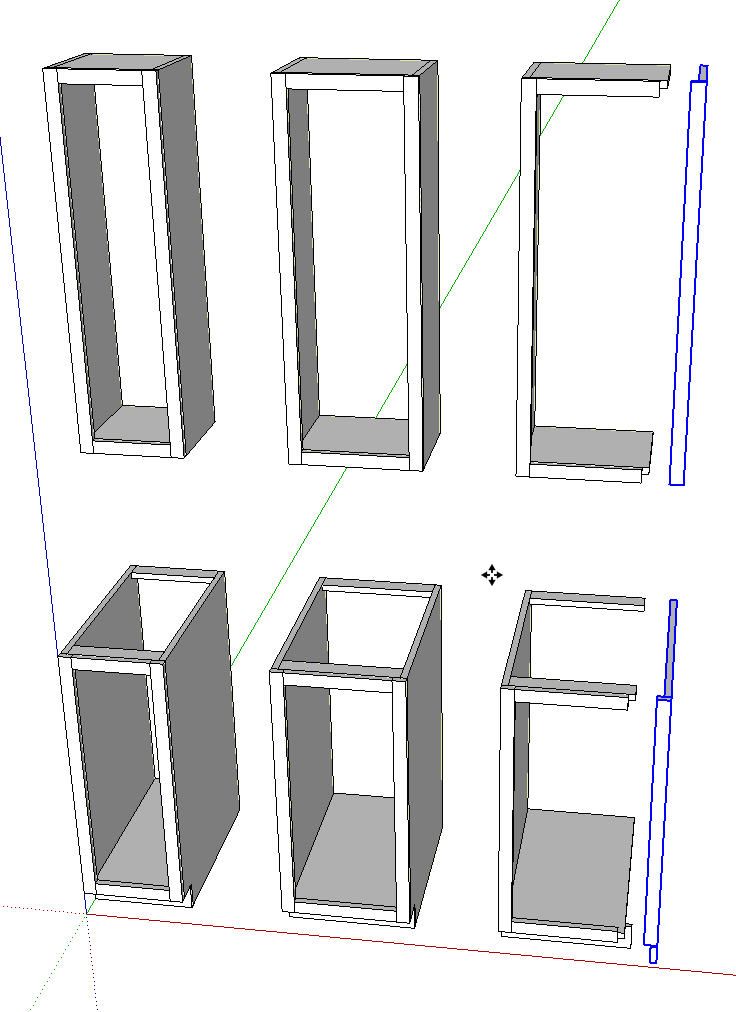
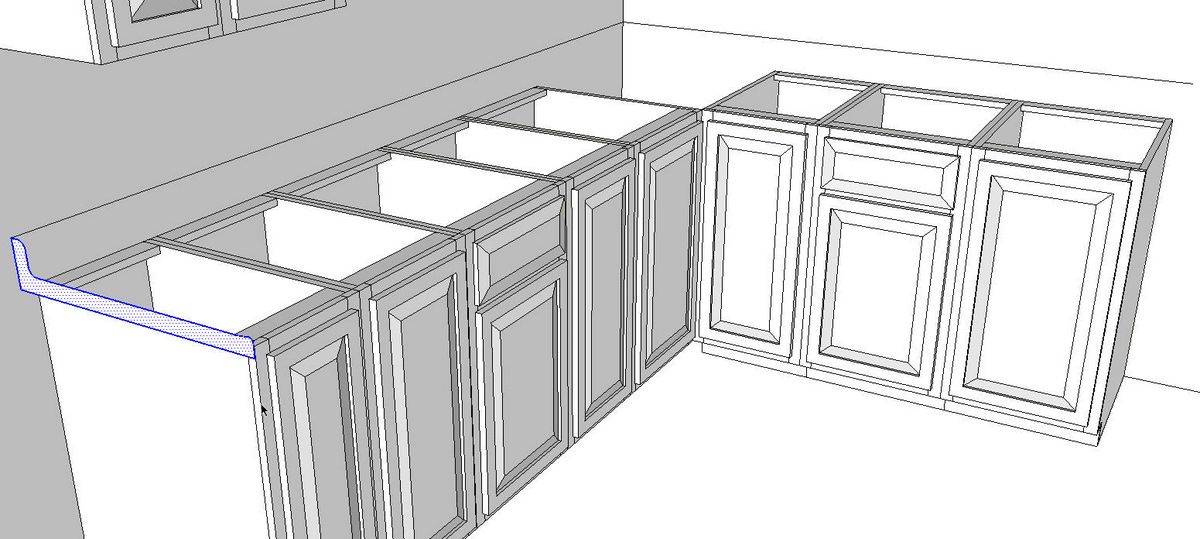
Now edit the horizontal components for the 15 inch cabinets. Push/Pull will make quick work of this. Once you pull the first face over 3 inches, you’ll be able to just double click with Push/Pull on the corresponding faces in the other components. Remember you’ll need to open one of each component for editing before using Push/Pull.
Since I set up gluing and the insertion point is at the back left of the first cabinet, I make all my changes on the right side for every cabinet.
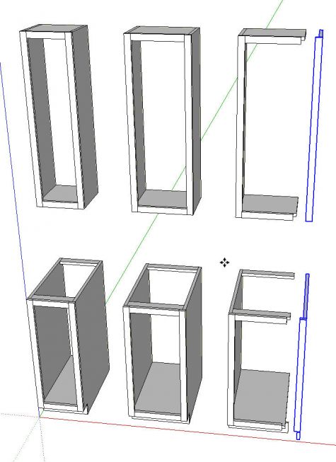
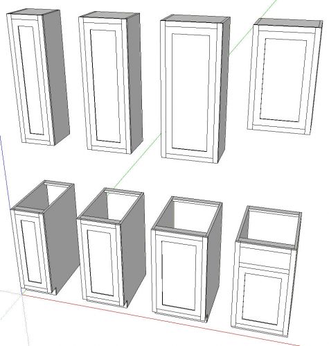
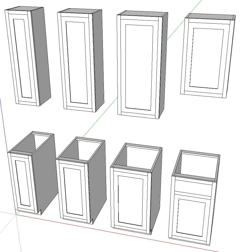
Repeat the process for the 18 inch wide cabinets.

I’ve made two versions of the 18 inch cabinets here. For this example I’m not going to make all the different standard sizes of cabinets. I think you’ll get the point. With all the cabinet cases made as components, it is time to move on to the doors.

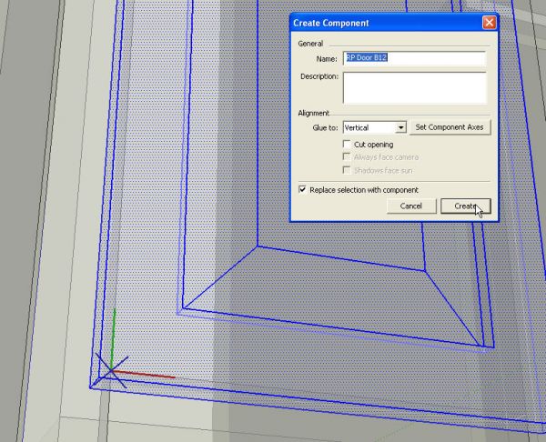
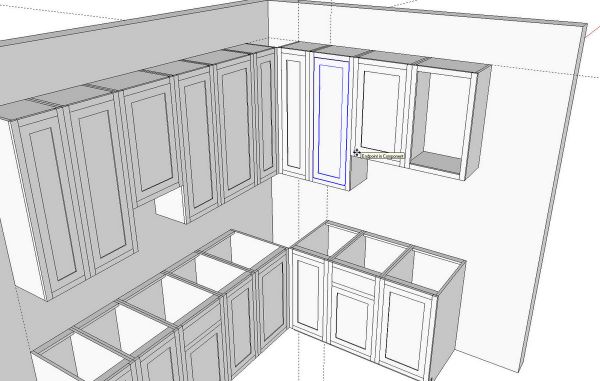
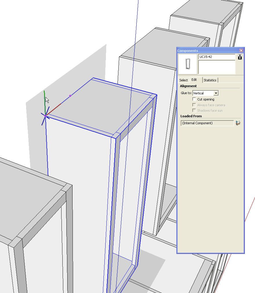
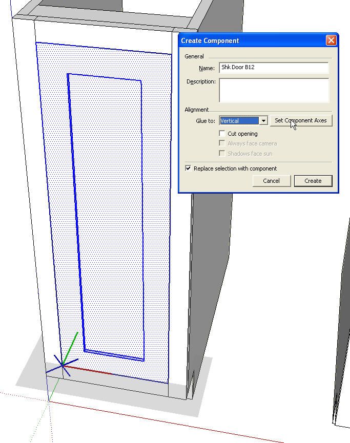
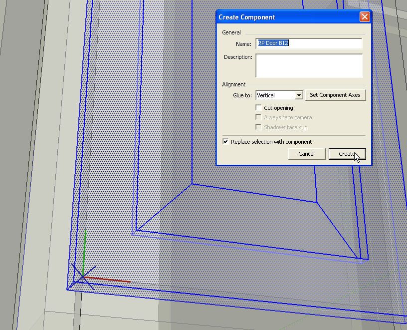
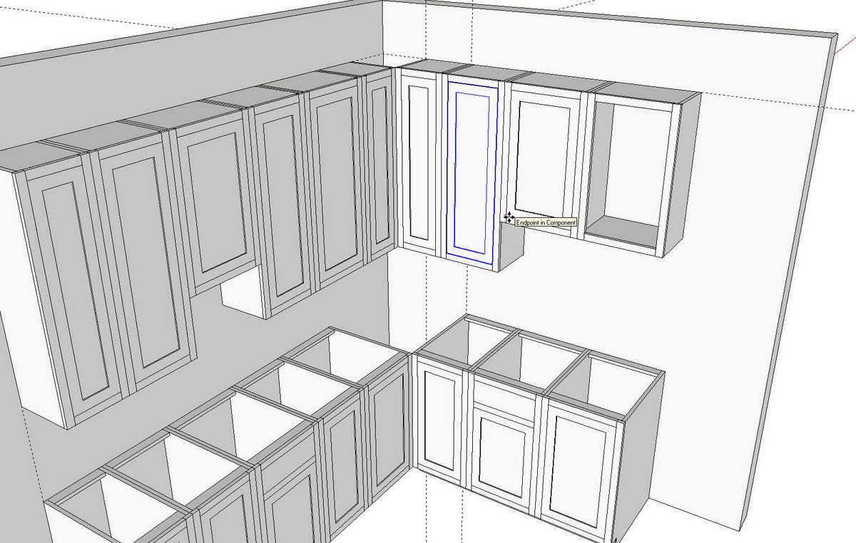
I’m not detailing the doors. I’m just creating basic doors under the assumption we’ll order them instead of making them ourselves. In the image above I’ve drawn a simple shaker inset door and I’m in the process of making it into a component. I’ve set Glue To: to Vertical. the gray rectangle shows the gluing plane and the axes show where the insertion point is. The gray rectangle and the blue X are indicative of a component that has gluing characteristics. Before clicking Create, we’ll click on Set Component Axes.
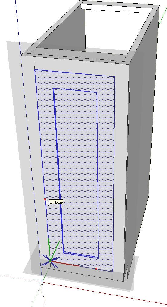
For this door we’ll set the origin at the front lower left corner with the red axis running across the bottom and the green axis running up the left side. In the image above you can see the orientation of the new gluing plane. After clicking to set the green axis the Make Component dialog box will reappear and you can click Create.
Now select this door component from the In Model components library and place a copy in the opening of the next cabinet. You’ll see the door just about places itself as you click on the lower left inside corner of the face frame. Right click on the door and make it unique. Then open it for editing, Drag a left to right selection box around the right half of the door and move that selection over to the right 3 inches. Adjust the name of the component in Entity Info. Repeat the process for all the rest of the doors. Also make drawer fronts as needed. Give them gluing characteristics just as you did for the doors.
Now you have cabinets and one style of doors and drawer fronts. Save these components as local collections for later use. See Save Components for Future Use for ideas on how to do that. For this example I made separate libraries titled Kitchen Base Cabs, Kitchen Upper Cabs, Shaker Doors and Raised Panel Doors.
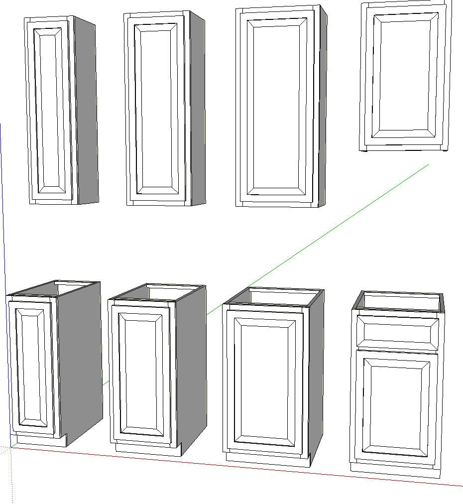
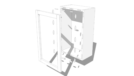
After making sure I’ve saved the shaker-style doors, I deleted them from the model. Then I went on to make some simple raised panel overlay doors.
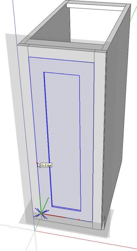
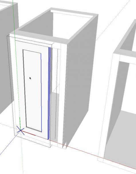
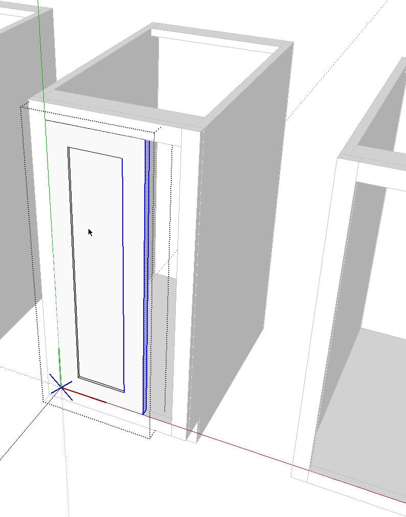
While making the first one a component I set up the Glue To properties and put the component’s insertion point at the same place as I did on the Shaker doors. I shifted to X-ray view to make it easier to see the corner of the face frame elements.
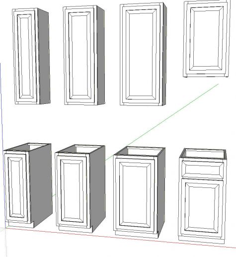
After making the first raised panel door component, I went through the process of inserting copies of it, making them unique and editing their dimensions as I did on the shaker doors. These doors then got saved out to the Raised Panel Doors library.
You could make as many different door styles as you want.

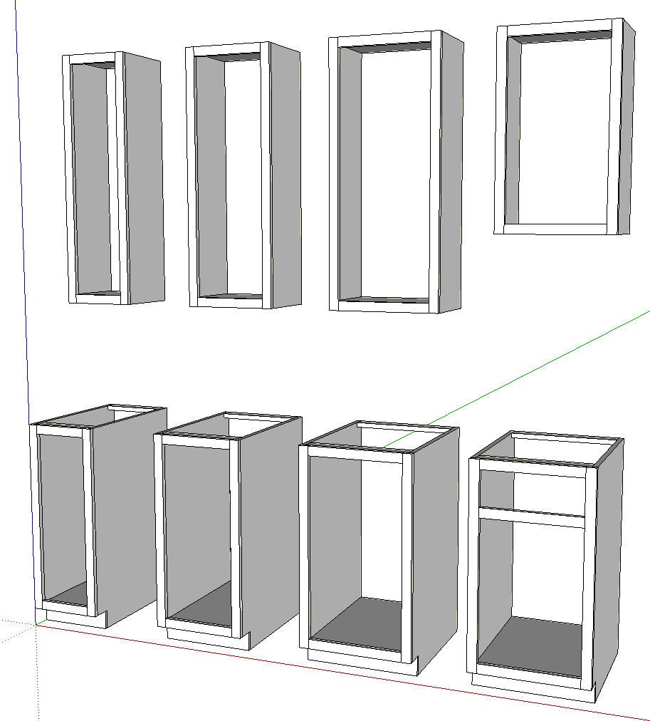
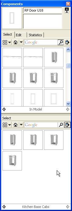
In the image above you can see that I’ve saved out the base cabinets to their own library. This library could be added to at any time so you don’t have to make all of the cabinets immediately. And if you customize a cabinet in a specific model, save a copy of it here for possible future use, too.
Now we’re ready to move on to laying out a kitchen. And lets suppose we want to show out client two door style options. We’re happy that they don’t want to see any other styles because we haven’t made them. 😉
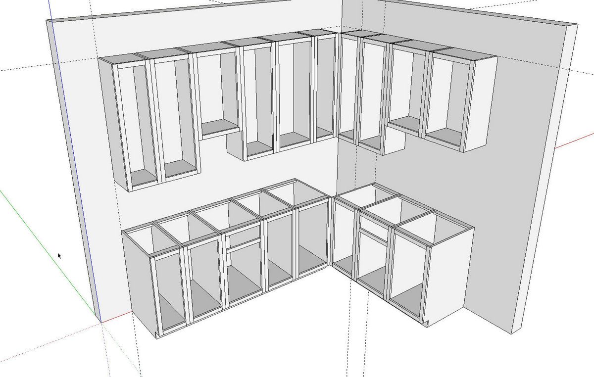
Here’s I’ve just drawn two walls. I set out a guideline representing the top of the upper cabinets. I also set out guidelines to identify the left end of each run. You can think of these guidelines as the chalk lines you might snap out if you were placing the cabinets in real life.
With the guidelines in place it was a simple matter of inserting the cabinets by selecting them from the appropriate library and sticking them in place. Since they were set up with gluing properties, there’s no need to rotate the cabinets to get them into place.
After placing the cabinets, I created a layer called ‘Cabinets’. I selected all of the cabinets and, in Entity Info, I associated them with that Cabinets layer.
I then inserted the shaker doors, created a Shaker Doors layer and associated those doors with that layer. Then I turned that layer’s visibility off.
I repeated the process for the raised panel doors as well.
A quick note about layers: I’ve talked about this a number of times but it bears repeating. Always leave Layer 0 as active. Always draw entities on Layer 0 and leave them there. Only create layer associations for components, text and dimensions.

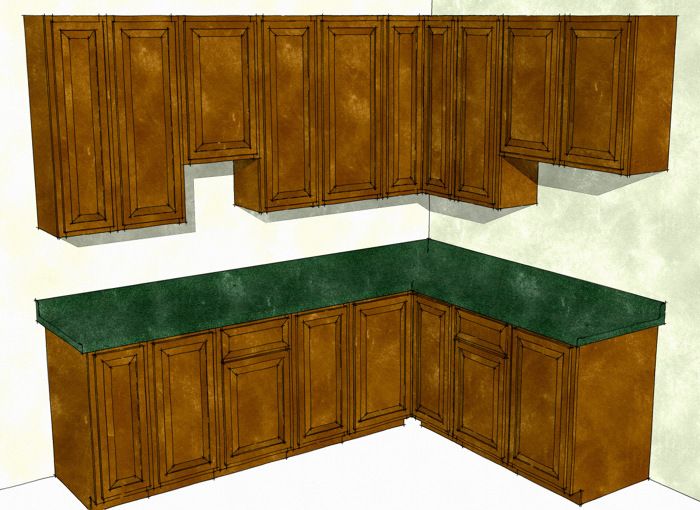
I’ve added a quick counter top using a profile and path with Follow Me. We could create simple straight runs of counter top and miter them at the corners which would be better if we wanted them included in the cutlist export.
After finishing up the model, we can create scenes to show different view points and the different doors.

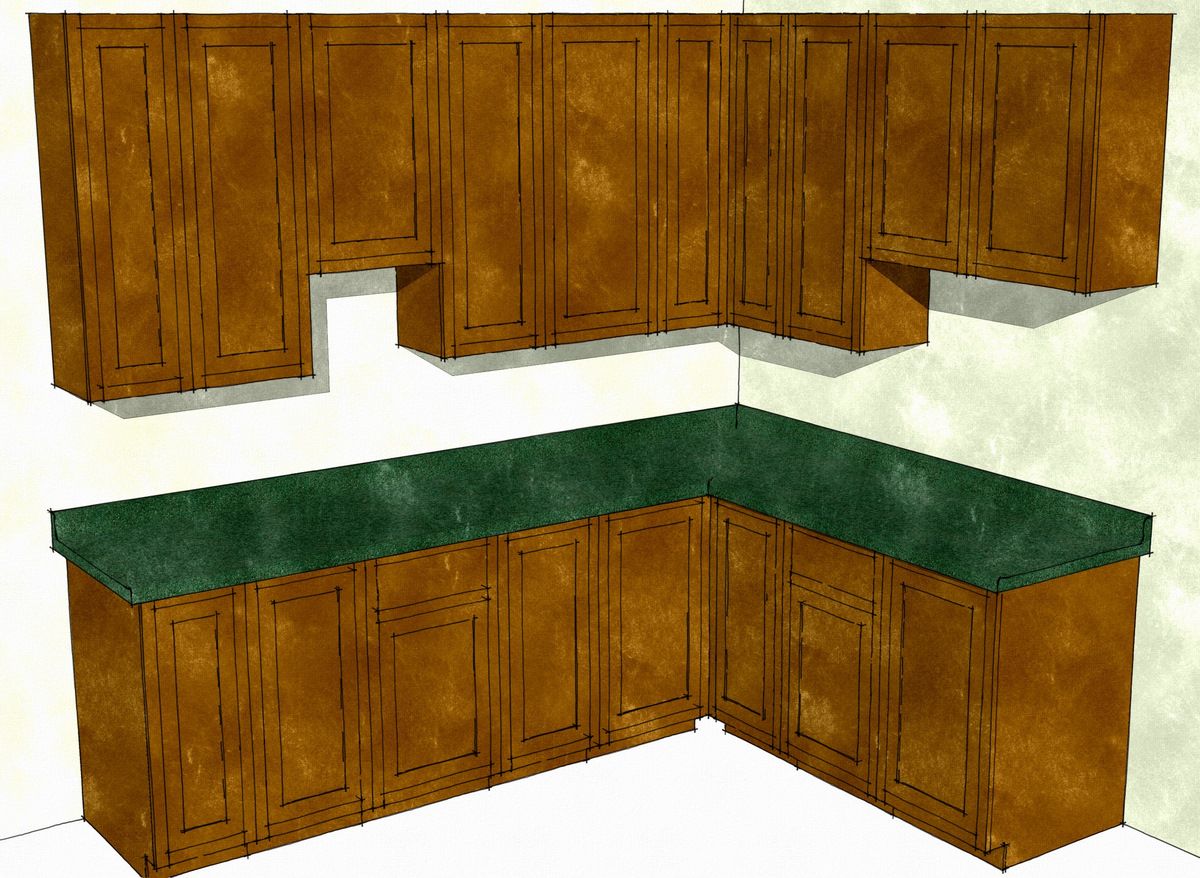
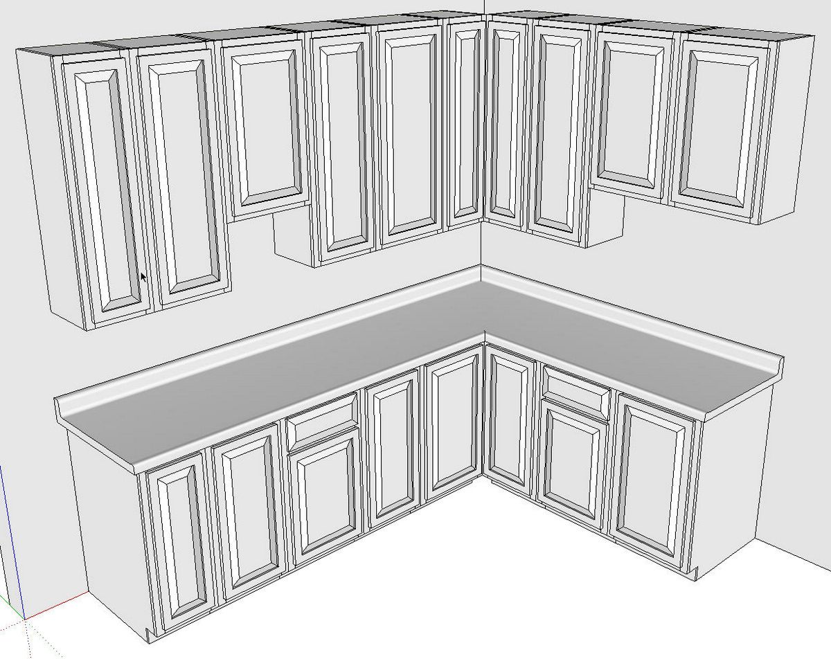
Here’s our cabinets with the shaker doors.

And here they are with the raised panel doors. After the client decides on the style of doors, you can run a cut list and figure out how much it cost.
You can create appliances, sinks and so on as needed. Sinks can be given gluing properties using the same process and can be set up to cut an opening in the top face of the counter top by checking the box for Cut Opening when you create the component. Note that the component will normally only cut an opening in one surface. If you delete the bottom face of the counter top component, this won’t be a problem. There is a plugin that will cut an opening in a second face that you could use but it may not be necessary.
Keep in mind that you can search Google’s 3D Warehouse for appliances and fixtures. You might also find useful cabinets that will work for you. You need to be discerning about the models you get from there, though. Some are good and some aren’t.
As far as the cutlist goes, make sure you add appropriate words to the component definition names or to the material names so the parts get sorted into the right sections of the cutlists.
None of this is really very difficult stuff but it does require some attention to detail. The more accurately you draw the cabinets in the first place, the easier it’ll be to insert them into your model and the better your cut list. Making the cabinets and doors may seem a bit tedious but you should only need to do it once and the time saved later can more than make up for the time spent up front.


Comments
Dave - I use SketchUp 8 and the wood color choices in the paint bucket are very limited. How do I get more options for different types of wood?
Hi Jeff,
I agree with you. The wood materials included with SketchUp are not that great. You can try doing Google image searches for the species you're after and sometimes find some usable wood grain images which can be imported into SketchUp. there are also sourse such as http://www.arroway-textures.com which offer high resolution images. I would suggested down-sampling high resolution images a bit to prevent file bloat.
-Dave
Jeff
There are at least a couple lumberjocks that have posted wood libraries
Jim Bertelson (I use Jim's)
http://lumberjocks.com/jbertelson/blog/12477
There is also this one which I haven't used
http://www.sawdustroad.com/sketchup
Thanks. I'd forgotten about those two. Jim Bertelson's library is not too bad although there's no need for both vertical and horizontal samples of each material.
I generally work with long images of wood grain materials that scale out to anywhere from 8 feet to 15 feet depending upon the species. The images typically range from 7 to 12 inches wide. This gives me the opportunity to pick and choose various parts of a "board" so the images don't obviously repeat.
Yes, the vertical and horizontal version are redundant. I believe Jim said at the time of making them available he wanted to do it this way so he didn't have to rotate the material. So it is the way he chooses to work and of course one shouldn't look a gift horse in the mouth...
While I have had Sketchup for quite some time, I could never get to first base with it. This changed when I ran across Timothy Killen's book "Sketchup Guide to Woodworkers". Now I feel I can move beyond my orthographic projection 2-D drawing that I have used for some time the 3-D approach. I would like to do something like this person did; however, I would like to include some more detail such as the stile and rail profiles that are not "rectangular" projections. In particular, I used the "FollowMe" tool to create both the "slot" on the edge of the rail and then the stub tenon on the end of the rail. I seemed to work; however, I ended up with an extrusion of curved surfaces where the stub tenon intersected with the side slot and I could not figure out how to get rid of it. I have been all the way through Killen's book and he did not address this. There must be a way around this, I just cannot find it. But then I only have a limited amount of experience with Sketchup.
Howard, drop me an e-mail at [email protected] and I'll gladly help you over this hump.
Howard, there's also this that ought to help but I'd still be glad to give you some assistance.
https://www.finewoodworking.com/item/30274/easy-and-easier-raised-panel-doors
-Dave
In a previous life I designed kitchens and baths using 20/20 software. Using the free Mac version of SketchUp, I designed a kitchen using the current footprint and wall space of the kitchen. Moldings can be drawn, cabinets offset to create visual interest, etc. I don't know how or where I can post the file to demonstrate. JeffB's observation about wood color choices certainly apply. I used the color and textures of the building materials that are available to create a faux granite top.
Drllucas, you are correct. All sorts of details can easily be added to the SketchUp model. And it makes it simple to explore various design ideas. Just as I show with changing door styles, different molding options or materials can be shown.
You bring up a good point about materials, too. Many manufacturers offer image samples of their materials that can be imported into SketchUp. Although it doesn't really show in the samll color images I made, the counter top has a Corian material applied to it. the cabinets and walls just have Pantone colors applied, however.
-Dave
Well I designed all my kitchen cabinets a few months ago and have pretty much finished building them and installing them. I didn't bother to go overboard with the textures but the detail level was enough to generate a Layout set wi dimensions, construction notes and cutlists. I put the SU doc in the warehouse at
http://sketchup.google.com/3dwarehouse/details?mid=36b8a3f3b84f026c1a65fb062aae4e37 should anyone be interested. I'll try to find somewhere to put the PDF of the Layout file...
Im new to Sketch up and use a v8. At the moment I am still learning the programme. The units on here look very comprehensive and show the beauty of Sketch up. I'm an oldie who retired and now make furniture on commisions. Mainly basic household items and garden furniture. I built my kitchen some time ago and working on the principle of if it's not there ask for it. So my question is why no corner unit, in UK they usually have a carousel unit inside. There is a lot of unused space in your corner. Possibly using an L shaped door on the front and developing the corner. I hate drawing but on Sketch up would it be possible to draw it. Maybe in 6 months I will be able to do this in Sketch up. Thanks for the great possible lay out Raymondj.
Raymond,
You could certainly draw a corner unit and the kitchen would benefit from it. This kitchen was only drawn to use as an example of how to make cabinet components so they are easy to work with when laying out the kitchen. At least I don't have any plans to install cabinets like that.
You're right that a corner unit would help to avoid wasting space although I can't tell you how much I dislike the corner unit in our kitchen. My opinion is that kitchens shouldn't have corners. ;)
—Dave
Log in or create an account to post a comment.
Sign up Log in