In Chapter 7 of my book, I present the first practice piece of furniture – the making of a Magazine Rack. Although it looks simple, this project has some challenges. Last week I posted a video on making the tongue & groove joints. This week I show the cutting of the ogee shape in the side. As usual, this requires careful placement of guidelines to help in the layout of the shaped-cutout. I also show a process for making an ogee shape using the Arc Tool.
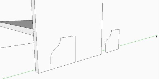
The cutout is symmetrical therefore you should make only half of the shape. Then copy this half, flip to mirror it, and attach to the first half. This same shape is also used in the front skirt of the magazine rack, so you can make a component of this shape to save for future use.
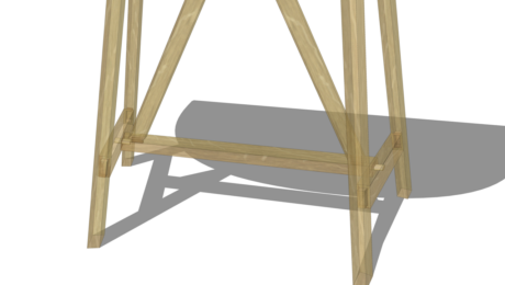
Here is a picture of the half-cutout and a copy moved down the green axis.

And here is the video……
P.S. I see now that the other side component was not modified automatically as it should have been. Now I realize that I had made the edited side a unique component and forgot to replace the other side with this new defined component name.


Comments
This quickly resolved a number of issues, and reinforced the principle that you ALWAYS need to use "Edit Component" when making changes. Also helped in being able to cleanly delete guidelines.
Hello Tim, I what to first compliment your outstanding SU for WW workbook. It really has motivated me to learn the software for my future projects. My question is the following. I am on chapter 9, step 19, creating the leg mortises. It seems when I created the legs and aligned them according to steps 4-6, I used the flip command. I see the results if the I do the flip command incorrectly. When I started the tenons on the front legs, I see them appear on the back legs (where I of coarse don't want them). Before I delete all my leg work and start all over, is there a quick way of correcting a leg that has been programmed to flip (undo) when I'm so far into the design? I don't think I want to create individual leg's because it would defeat the purpose of the exercise (creating legs in the right direction so I can capitalize on creating tenons). Your advise please. Is the best way to go back to square one? I also wanted to mention I will be looking forward to your possible second module...what do you think? Great job!
Josea: I don't think you have done anything wrong here. It seems I should have emphasized the need to make the back legs separate components. The back legs will have different mortises than the front legs, so it is necessary to make the back legs unique from the front legs.
I would make the back legs unique after the chamfers are made .... say after Step 11 on page 48. To make this change I would use the following procedure:
1. Select one of the back legs. Right click and pick Explode from the pop up menu
2. Right click again on the already selected leg and pick Make Component from the pop up menu.
3. Name the new component Back Leg in the dialog box
4. Replace the other back leg with the new Back Leg Component. This will require a "Flip Along"
Let me know if you have any problem with this. And congratulations in getting this far in the book.
I think I will do a video on this area of Chapter 9 next week.
Thanks for the feedback.
Tim
This definitely helped my get further along in Chapter 7 of Killen's Sketchup Guide. Unfortunately, I got stuck on drawing the Front Skirt of the magazine rack. I must have done something wrong because I was unable to complete Step 9, push/pull of the rectangle defining the front face of the Front Skirt. When hovering over this rectangle with the push/pull tool, a blue diamond would appear above the push/pull tool. I have searched the web for an explanation of what the blue diamond means. Any suggestions would be appreciated.
bfblack: I'm perplexed by your seeing a "blue diamond" above the Push/Pull Tool cursor. I have not seen one of those.
If you simply draw a rectangle off in space, then pick the Push/Pull Tool and hover over the face, do you see this strange blue diamond?
When hovering, the face ordinarily changes to a highlighted dotted texture. Or if it is a component, and you hover without opening the component for editing, you will see a standard "No" icon above the cursor. That is, one of those red circles with a slash.
Perhaps the graphics card in your computer is doing something strange. To check this, you can turn off "hardware acceleration" in the Preferences Settings.
Tim
Log in or create an account to post a comment.
Sign up Log in