
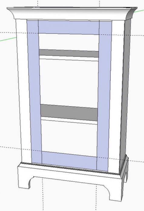
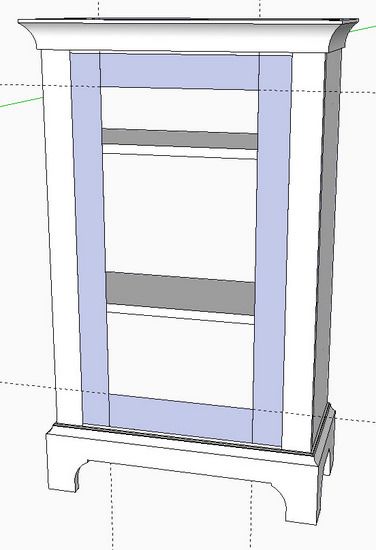
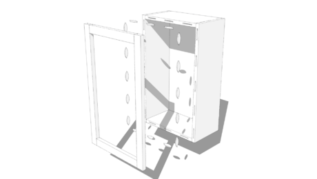
Here is a small colonial cupboard that was presented in a Fine Woodworking article in issue #151. Although appearing simple, this little piece has some complex but classic features. One of those is the paneled door having a 1/4-in. thumbnail around the inner perimeter of the stiles and rails. Often, I see modern implementations having a separate molding frame inserted into that inner perimeter. However, I like to do these things in the classic way, and I’m showing that in the following steps.
After placing guide lines for the their widths, use the Line Tool to draw in the stiles and rails shown in blue. Create components from these faces for the stile, lower rail, and upper rail.
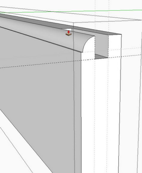
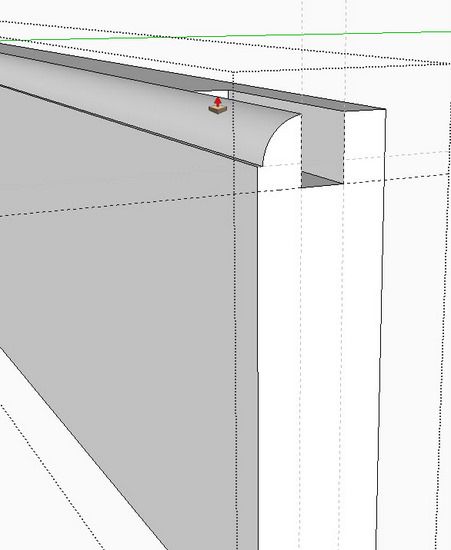
Copy over the lower rail away from the assembled model to work on temporarily. Place guide lines and draw the shape of the thumbnail molding and the groove as shown below. Use the Push/Pull tool to push each shape throughout its length.
In the same way, make the thumbnail and groove for the stile and the upper rail components.
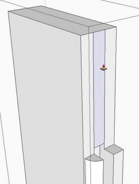
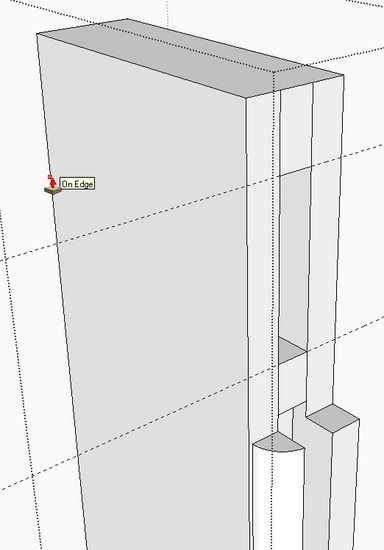
To make the mortises in the stile, first push a 1/4-in. waste from the inner edge of the stile. After drawing short lines on the top end, use the Push/Pull Tool to remove the waste down to a guide line that is the width of the top rail minus the 1/4-in. thumbnail or 2 1/4-in.
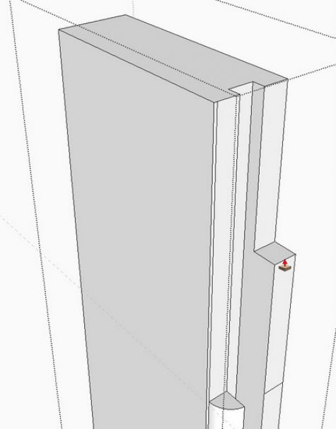
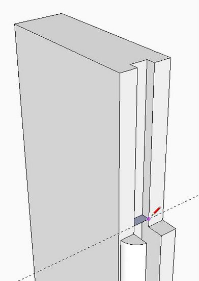
In the shop, you would need to route a stopped groove in the stile to avoid a gap at the top end. We could have done a stopped groove in SketchUp, but I think it is easier to run the groove through to the end, then backtrack as shown in this step.
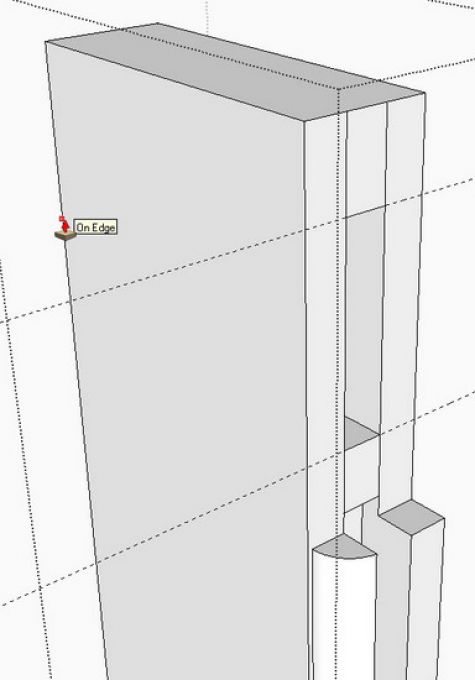
Place a guideline about 1/8-in. up from the end of the thumbnail. Use the Line Tool to create a stopped face that will provide sufficient space for the panel at the corner. You don’t need a face rather a single line down in the root of the groove would work. But the guideline causes me to start on the face and then I’m sure that the line at the root is the correct distance from the top face of the thumbnail.
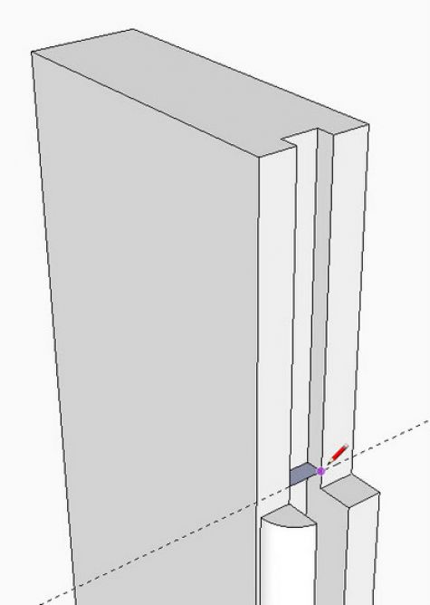
Use the Push/Pull Tool to pull out the bottom of the groove flush with the inner face of the stile.
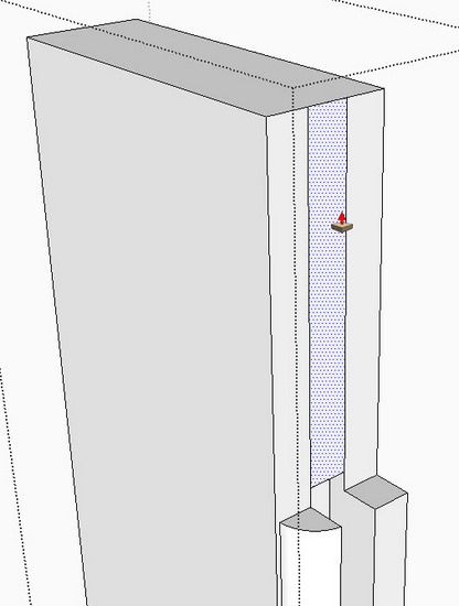
Mark out the length of the mortise with guide lines. Draw lines for the top and bottom of the mortise, then push out to the back edge of the stile. Use the Eraser Tool to remove the unnecessary vertical lines.
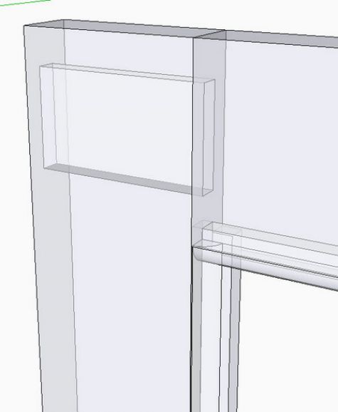
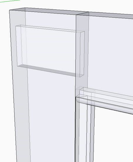
Connect the top rail to the stile as shown in the x-ray view below. In the x-ray view, create the tenon in the top rail.
Use this same procedure to create the tenons in both ends of the top and bottom rails.
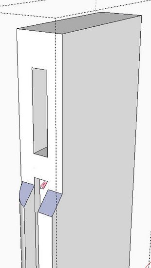
The next procedure is to create the miter joints for the thumbnail molding in the inner corners. We’ll need to use the Intersection function to cut the molding in a 45 degree angle.
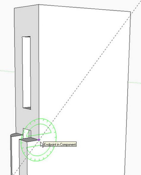
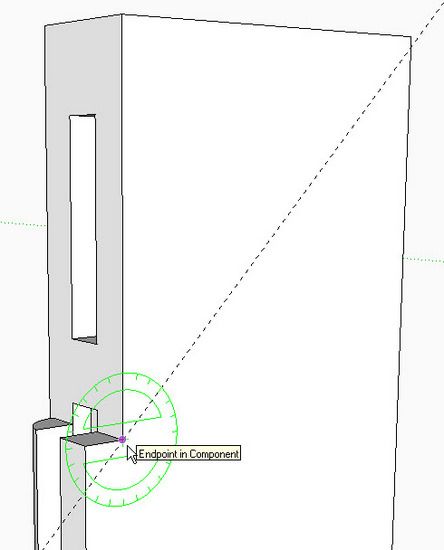
Orbit around to the back side of the stile. Position the Protractor at the corner as shown below and draw a 45 degree guide line.
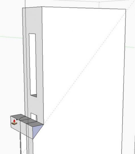
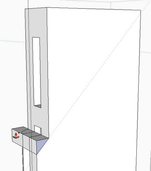
Trace over the guide line with the Line Tool. Then pick the Push/Pull Tool and hit the Ctrl Key (Option on the Mac). A small + sign will appear on the mouse cursor. Push the triangular shape beyond the front edge of the stile.
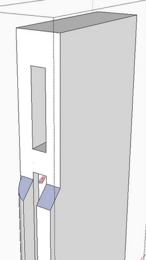
Use the Select Tool to draw a select box around the miter joint. Right click on the selection and pick Intersect with Model.
Use the Eraser Tool to clean up the waste after the Intersection. This completes the creation of the miter at this location. Repeat at the lower joint, and also perform this procedure on each end of the top and bottom rails.
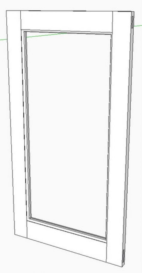
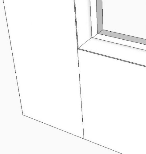
Here is a close-up of a very good miter joint.
Next time, I’ll cover how I do a beveled panel for this door frame.


Log in or create an account to post a comment.
Sign up Log in