
Reader Erick asked about drawing dovetails in SketchUp. Here’s a quick and simple way to create dovetails. In this example I’m showing the dovetails as being the same on all four corners. For something like a drawer with half blind dovetails on the front, you would you would have a separate layout for the front and back but the process is the same.
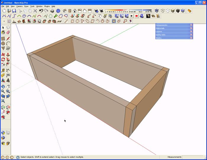
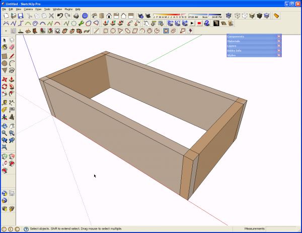
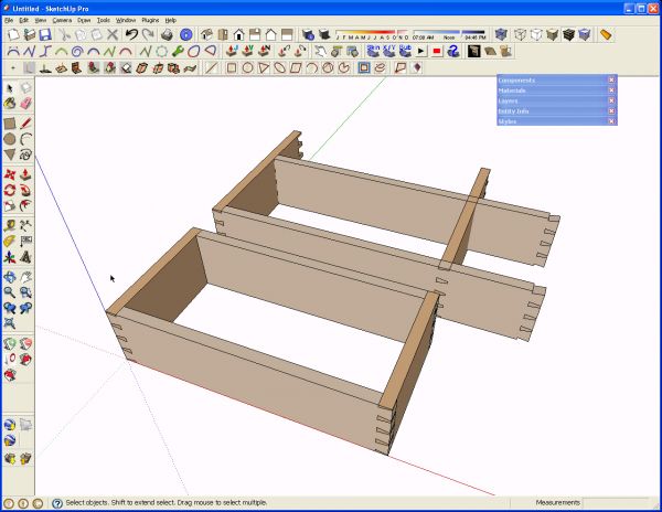
To start with I drew the four sides for the box. Well, I drew a side and an end. I made these components and then copied them with Ctrl+Move to make the opoosite parts. The copies were flipped or mirrored rather than rotated. Notice that the parts are drawn just as they’d be made in wood to the outside dimensions of the box.
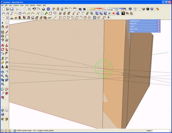
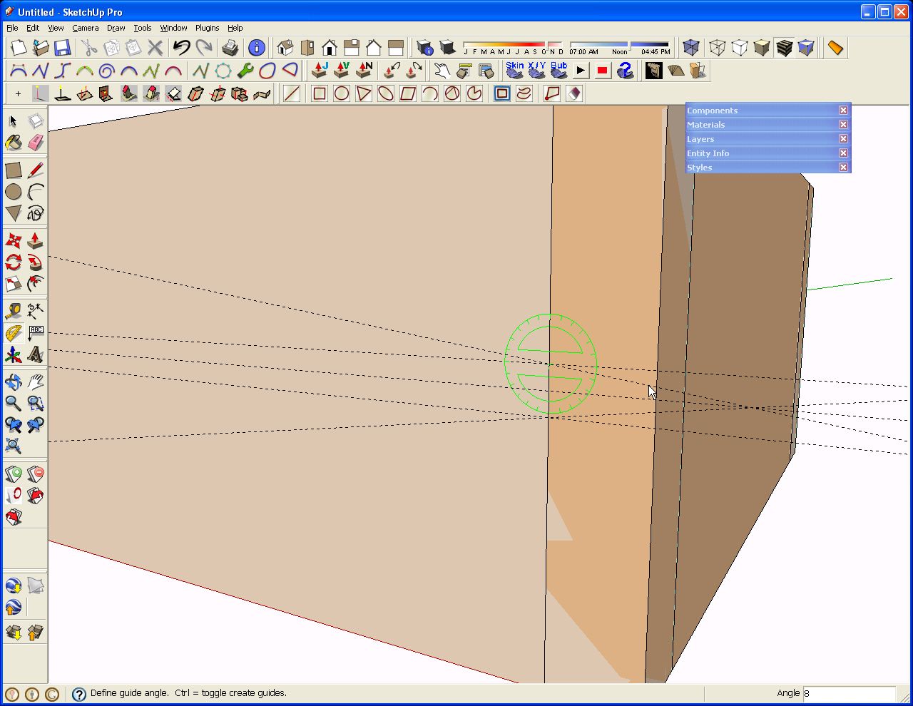
For this example I am doing a simple, even layout of the dovetails. I like to have a pin on the centerline so that’s where I start with the layout. I put in a guideline on the centerline by dragging down from the top edge with the Tape Measure tool. Of course you could drag up from the bottom, too. After clicking on the edge of the box side with the tool, drag up or down along the outside corner until the cursor snaps at the midpoint. Click there to set the guideline. After the centerline is indicated I added a couple at 1/4″ on either side and at the intersections of those lines and the inside edge of the end of the box, I placed a couple of angled guides with the yellow Protractor tool. I put these in at 8° but if you prefer to work in rise over run sorts of numbers you could enter a value such as 1:7. This is all the layout we need in this case. Notice that this is done with neither component open for editing.
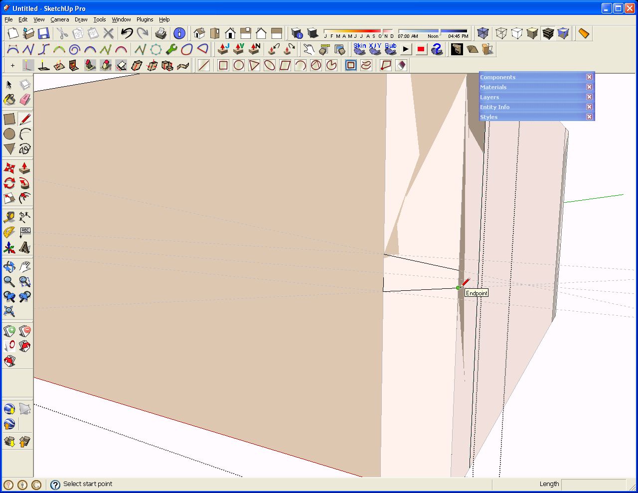
Next, because I’m a tails first guy, I opened the side component for editing. I used the Line tool to trace the guidelines to outline the center socket.

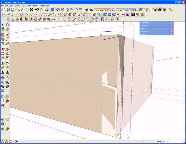
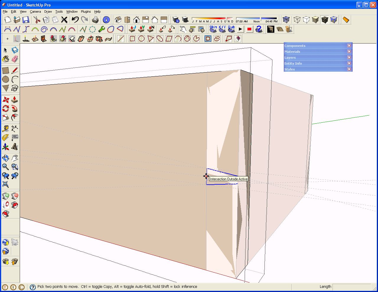
Next I select the three line segments I just drew and then got the Move tool. I hit Ctrl to invoke the Copy command and then grabbed the selected lines at the centerline–the midpoint of the bottom of the socket.

Then I dragged the copy of the lines up until the tool was on the top edge of the box. This leaves me with a half socket at the top.
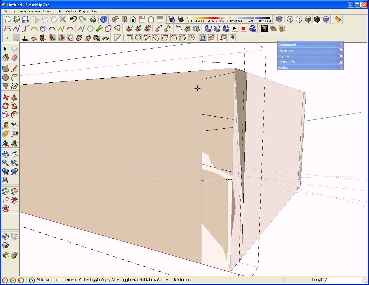
I hit enter followed by /2, Enter. This makes two copies of the selected lines with the spacing being even between the first (center) and last (top).

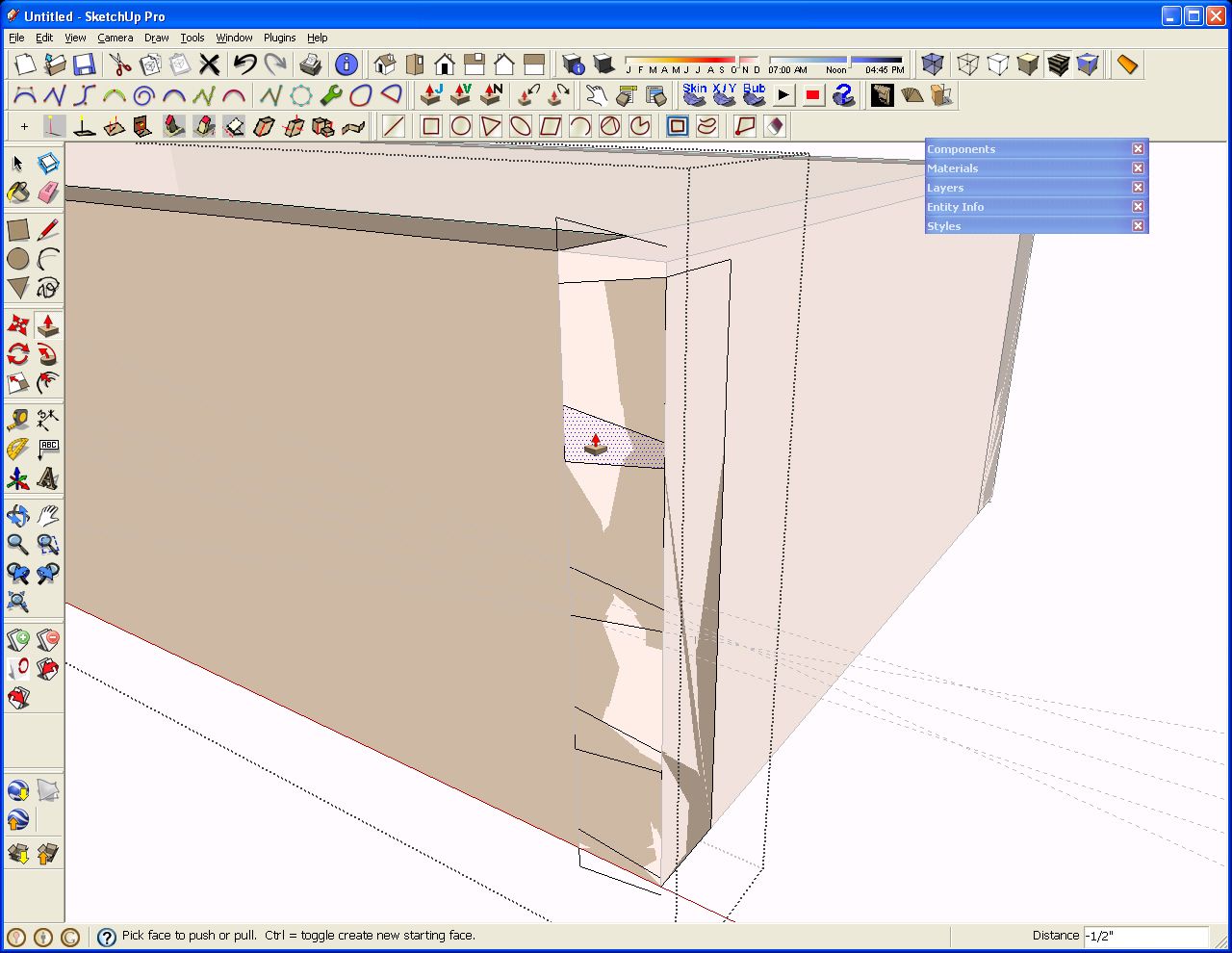
I repeated those steps for the bottom sockets and then start in with Push/Pull to get rid of the waste. Remember which side of the joint you’re working on when you do this. After pushing in the top half socket, double clicking with the Push/Pull tool on the other sockets results in those sockets being cleared as well.
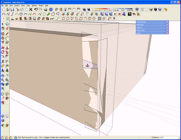
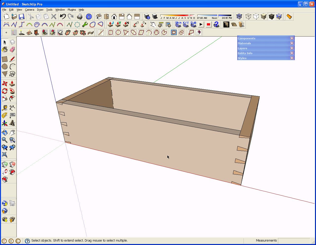
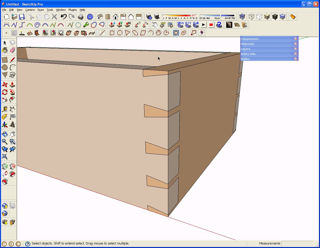
When that is finished, the tails on this end of both side pieces are complete.
So now, just as you’d do in wood, we’ll trace the sockets onto the pin board. Open the end component for editing. Use the Line tool for this instead of a marking knife. You could also select the angled lines of the sockets and copy them with the Copy command, not Ctrl+Move, and then use the Paste in place command from the edit menu on the opened End component. In this situation it probably doesn’t save you any time though. Intersect may work but due to the coplanar faces, it isn’t reliable. Than Push/Pull on the end of the board to clear the waste between the pins. You can still use the double click with the Push/Pull if the ends and sides are the same thickness.
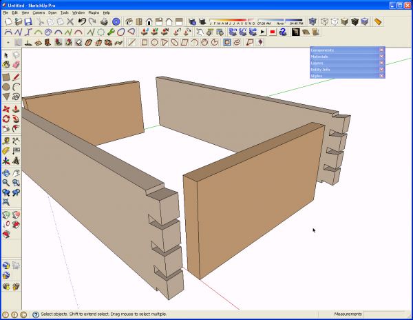
Orbit around to the opposite end of the end component and repeat the operation and then open one of the side components, trace the pins and Push/Pull the waste. This is for the pins first crowd. Now all of the joints are complete.
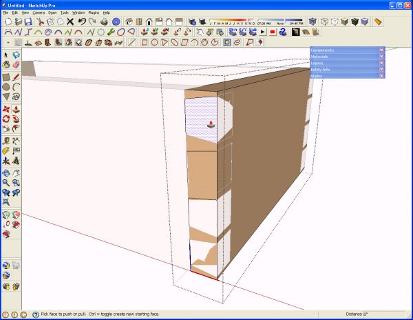
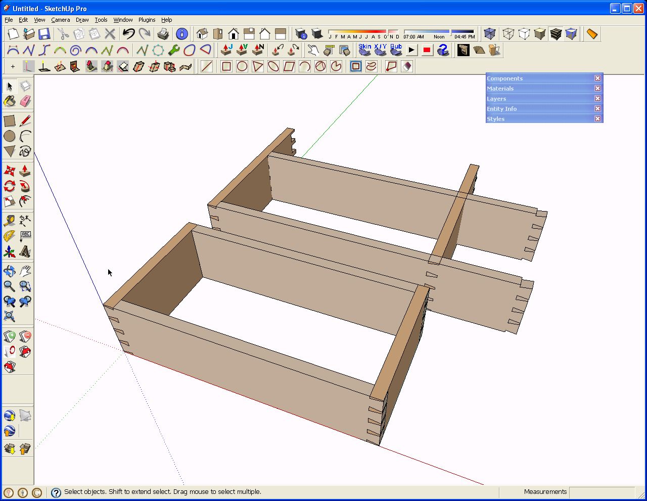
Near the beginning of this blog post I mentioned that I flipped or mirrored the copies of the side and end components. The following images illustrate why. With one drawer box complete, it is a simple matter of editing a copy of it to make one of a different size. Here I am showing the sides extended 4″ and the ends 3″. I opened one side component for editing and dragged a left to right selection box around the joinery at the end. Then I used the Move tool to move the selection 4″ to the right. I repeated this on the end component. All that remains is to move the components out to align the corners again.
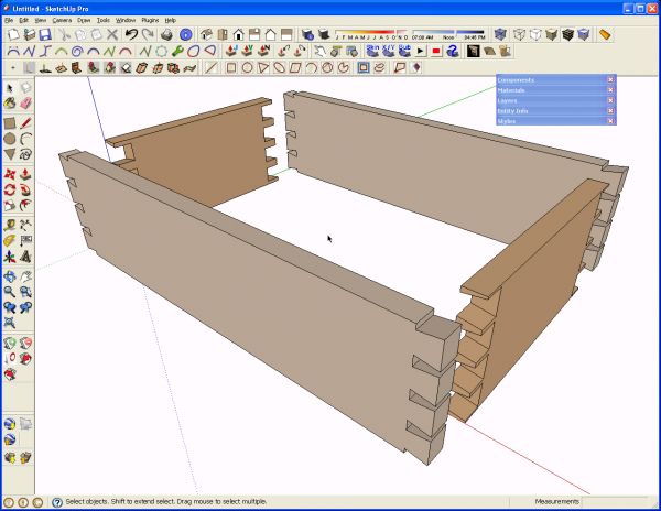
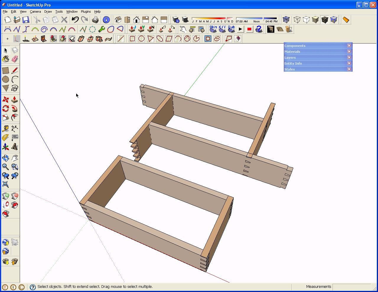
In the next image I rotated the copies of the side and end components end for end. This seems like a reasonable thing to do. You’d do that in wood afterall. Notice what happens when the components get resized though. It’s not the end of the world be now thereis extra work involved to get the corners aligned correctly.

So there you have it. A dovetailed box.As usual, if you have questions be sure to ask.


Comments
seems like way too much work
NHLawer, have you got an easier method?
Dave,
Once again, you show why "you da man". Not only is your description easy to follow, but I'm equally impressed at how quickly you responded to my question.
Thanks for the quick lesson.
Erick
Hi, I'm new here, but started reading this forum because I've been using SketchUp to design my woodworking projects.
I had to do some dovetails a couple weeks ago, and it would have been nice to have this info. I didn't make mine even, and had to redo them when I flipped the copied board over.
I've tried a few different things. After "cutting" the tails, I used the intersect tool to cut the pins. However, it was unpredictable as to whether or not this would actually work, and I never figured out what I did when it did work.
I also needed to copy and resize a board with dovetails on it. I spent time pushing back each face, but in the end had trouble getting them all to work right. Quite accidentally I discovered you could select the end of the board and use move to resize it. You can either start it in the direction you want to go and type in an offset, or make a mark with the tape measure and push/pull it to there.
David
Erick, glad to help. Just call me "speedy". No wait. That'll set me up. ;)
David, my apologies for not doing this sooner. Had I known...
Dave
Dovetails always seem to be made as you've drawn w/ a half pin at the top and bottom. But why. If the drawer face is left exposed it makes a not particularly pleasing pattern of different sized bars on the face that manages not to make a mark at the corner.
By accident I laid out the tails starting with a tail at top and bottom that grew in width as it moved toward the face. It would be as if you took your tails and flipped them front to back. Then I laid out a series of thin tails that make fat pins. The end pattern on the face is of a series of evenly spaced squares that start and stop at the corners.
I would attach a pdf file or a sketch model, but there seems to be no way to include them
Your skill with the program is far beyond mine, but I find sketch most useful as a tool to consider alternatives, slight variations and to convince myself that the project will be worth the effort to make it real. And even then, things change in the basement.
Dave, this would be a good one to do a video on. Seeing how you navigate the model, use scale tool to invert things, and generally work it to lay out something helps others gain confidence with the program. After reading all day its nice to sit back and get an understanding by watching. Either way, as always I look forward to your posts.
PSeverin,
the reason I was told for half pins rather than half tails at the ends of a run of dovetails is that there's better control over the pieces if they choose to cup. The pin board can't go very far at the edges for the same reason the tailboard can't be pulled out that direction. The Tailboard can't go anyway because you have a good long grain glue surface between the half pin and the tail.
If you place tails at the ends, you don't get those benefits.
Paul, I'll try to get a video done for you and post it. Thank you for the support.
Dave
Re plugins. I followed your suggestions. Still no Plugins menu. In my Preferences, Extensions, there are two choices,Dynamic Components abd Sandbox tools. Should there be others.
Hoop36,
Posting the comment once would be plenty.
You should also have Ruby Script Examples. I would see about getting a fresh download of the program and reinstalling SU7
Can't you simply use the scale tool to resize your drawer? That way you can have a drawer of any size in your componants and pull it out, resize it and voila it's ready to use.
Yes, you could use the Scale tool if you don't mind changing the scaling on the joints as well. Suppose you scaled the box sides to be 50% longer. You would also increase the height of the tails/sockets and change the angles in the joints. Then you'd need to scale the thickness of the front and back (the pin boards) to compensate. If you used the Scale tool to make the drawer deeper, the tails, sockets and pins would get wider and the angles would increase. If there was a groove for the bottom panel, it would get wider.
If you drew the first drawer box for, suppose, a chest of drawers and then used the Scale tool to make all the other drawer sizes in the case, you'd end up with different joints for every different size of drawer. You'd also end up with different thicknesses for some of the parts. I think traditionally the drawer stock would be planed to the same thickness for all of the drawers unless there are some very tiny or very large drawers in the project.
I tried to do this on my own a few weeks ago and was dissuaded by the number of steps involved. I was trying to layout everything by hand and it just seemed that there had to be some simplifications I was missing. The description of the process makes a lot of sense once I've gone through it all a couple of times. The use of the array capabilities for the initial pin layout and the guides makes things much simpler than I was trying to make it.
I did run into one thing that wasn't covered in the example though and am thinking that maybe I did something wrong. When I went to push the top and bottom half pins SketchUp drew surfaces for the missing half of the pins. I then tried to erase them, but since the surfaces were full pin sizes on the ends (the part that is endgrain on the drawer sides) that didn't work out so well. My solution was to intersect the 3 lines for the each of the half pins with the model and then cleanup with the eraser after the push/pull.
So what *should* I have done?
ifkerby, My guess is that you are still using version 6. Is that correct? If so, there is an added step that I left out of the process. The quickest thing to do would be to draw a line with the Line tool along the end of the board so that it intersects with the vertical line. That will result in breaking the vertical line. then Push/Pull will work correctly on the end of the half pin.
With version 7 this step is unneeded because the intersection is done automatically.
HOpe that helps.
Dave
Yes, I'm still using SU6. I downloaded SU7 a while back but haven't yet updated to the new version. Guess I'll go do that now.
Thanks!
I have just started to use SketchUp. So far I am really happy with what it can do. I wish you had a tutorial that I could download that would actually teach us the skills this tutorial is covering. Something similar to the self-paced tutorials I can download from Google to teach me how to use SketchUp.
The reason I state this is that I am not seeing the waste removed for my pins when I use the Push-Pull tool. I am using SketchUp 7. When I edit the component I find the push pull tool makes the entire side thinner instead of removing the waste. I am not sure if the issue is due to how I initially constructed my box or not. Is there a way for me to upload my project for others to comment on?
Hi Dave,
I can't believe no one has automated this yet with a plugin. Shouldn't this be possible? Select the ends of the components to join, specify angle, number of pins, etc and have the plugin do the rest. That would seem easier to me.
storri, it sounds to me that you haven't opened the component for editing prior to drawing the lines for the dovetails.
I'm not certain about uploading tutorial files but I'll look into it.
daltxguy, I suppose there's not been enough demand or someone would have done so. When the weather starts to cool off for you, perhaps you would do it? Hint, hint.
Log in or create an account to post a comment.
Sign up Log in