It seems a paradox, while producing a complete detailed 3D model, there still is a benefit to having the old standby top, end, and front orthographic view. In the beginning with SketchUp, I abandoned the standard orthographic views (the traditional product of 2D drafting), and worked in the shop with the more realistic perspective displays only. These much richer views provided a substantial upgrade in the readability of the component and joint details. However, as I would assemble these parts in the shop, I would miss having the full assembled orthographic front, side, and top views. For example, I would want to check the plumb-line dimension from floor to seat or arm level. Or I wanted to see the dimension across a chair from arm-to-arm. I suppose these types of dimensions could be shown in perspective, but somehow this doesn’t work well for me.
So I found a simple way of making the orthographic views from the assembled model. I’ll show this method in the following steps using a Shaker Rocker that I’m working now.
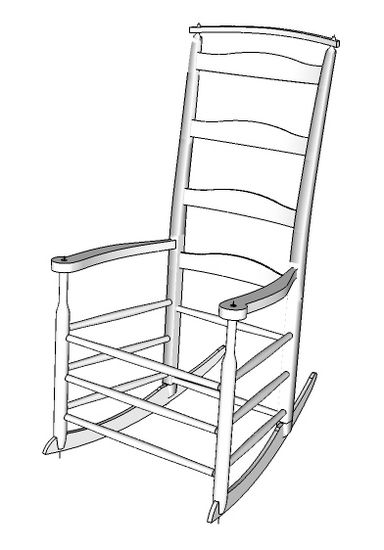
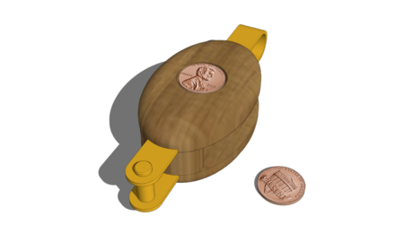
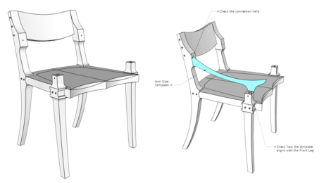
Here is the completed model of the Shaker Rocker.

Step 1: With the Select Tool, draw a left-to-right select box around the complete chair assembly. Right click on the selection and pick Make a Component from the pop-up menu. I use the same name for this component in all of my models, “Assembly”.
Step 2: With the Move/Copy Tool, copy the Assembly over to the side down the axis. Zoom in to this copy and create a Scene called “Orthographic View”. To make a Scene, click on the Window Tab and pick Scenes from the menu. In the pop-up menu, click on the plus icon to create a new scene. Type in the Name of the new scene “Orthographic View”. Click on the “Update Scene” icon which looks like two arrows chasing each other in a circle.
Step 3: With the Move/Copy Tool, make another copy of the assembly and move it to the right of the original. Make sure to move this copy on the axis. This copy will be made into a side or end view.
Step 4: With the Move/Copy Tool, hover over this new copy from the top. You may need to orbit to look down on the copy. As you hover over the component, two rotate origins will appear as plus signs. Place your mouse over one of these origins and a compass will appear. Rotate the component 90 degrees clockwise.
Step 5: Copy the original assembled component again and move this new copy up the blue axis. This copy will become the top view.
Step 6: With the Move/Copy Tool, hover over the side of this new copy. Again you may need to orbit slightly. Find the rotate origin and rotate the copy counterclockwise 90 degrees.
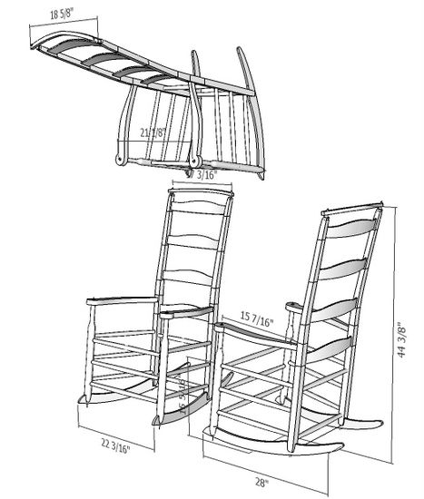
Here is the view of the three copies that you should now have:

Step 7: Click on the Camera Tab and select Standard Views from the menu. Click on Front in the pop-up menu. This will change the camera to Front View.
Step 8: Click on the Camera Tab again and select Parallel Projection. Use Zoom and Pan to get the best sizing of the objects in the window. Now click on Window and select Scenes. In the Scene pop-up menu click on the Orthographic View Scene, then save the view, by clicking on the update icon.
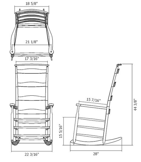
Here is the result. Add critical overall dimensions that will be helpful in checking the assembly in the shop.

Since the assembly is saved as a component, any change in the individual nested components elsewhere in the design file, will automatically be reflected in your saved Orthographic View Scene.


Comments
I too find ortho views useful - however, I use Jim Folz's MakeOrthoViews.rb plugin - one click on your selected model or component and you have a super set of ortho views.
This is where the Pro version is worth paying for; it's so easy to use Layout to produce full sets of drawings with views, details, annotations, whatever. Print to pdf to share or take to the printshop for large sheet paper copies. I've done a couple of pieces on LumberJocks; no idea if non-members can get to them but let's see-
http://lumberjocks.com/projects/24706 (a bookcase)
http://lumberjocks.com/projects/24185 ( a bed)
Log in or create an account to post a comment.
Sign up Log in